Introduction
Installing this kit is simple and straightforward. Once complete, changing your accessory belt will be quick and easy. Also, keeping your belt properly tensioned will be hassle-free. Installation is easiest
with the motor removed from the vehicle. However, installing the kit on a motor that has already been installed is painless and requires no special steps.
-
-
Before installing this kit, the a/c compressor, power steering pump, alternator, and factory belt tensioner must be removed. Cars that do not come equipped with a belt-driven power steering pump (such as the EP3) will have an idler pulley in the power steering pump’s place.
-
This pulley will need to be removed. Figure 1a shows the accessories that must be removed. See page 2 for details regarding bolt locations.
-
Figure 1b shows the two (2) bolts that support the power steering pump as well as the three (3) bolts that support the belt tensioner. Figure 1c shows the three (3) bolts that are used to mount the alternator, as well as the four (4) bolts that are used to mount the A/C compressor.
-
All of these bolts should require a 12 mm socket. Once the A/C compressor has been removed, the aluminum bracket where it was mounted to must be unbolted. Once you are complete with Step 1, the only pulleys still attached to the motor should be the crank pulley and water pump pulley.
-
-
-
Once Step 1 has been completed, the autotensioner can be installed. Figure 2b shows the 45 mm M8x1.25 bolt being inserted into the top of the autotensioner. This bolt should thread into the hole that the upper alternator bolt originally went into.
-
Figure 2c shows the 20 mm M8x1.25 bolt being installed in the lower mounting hole on the autotensioner. This bolt should thread into the left lower hole that the alternator was originally mounted to. Both bolts can be tightened using a 6 mm allen driver.
-
Torque both M8 bolts to 35 lbft (dry) or 28 lb-ft (lubricated with oil). Failure to properly torque bolts can result in premature fatigue or loosening of the bolts. (Note: color of bolts may vary)
-
One of the unique features about this autotensioner is that it’s designed to use different belt sizes without compromising performance by maintaining proper belt tension through an adjustable spring housing.
-
Figure 2d shows the 3 bolts that must be removed to adjust the spring housing. The bolts are an M8x1.25 thread and can be removed using a 6mm allen driver.
-
-
-
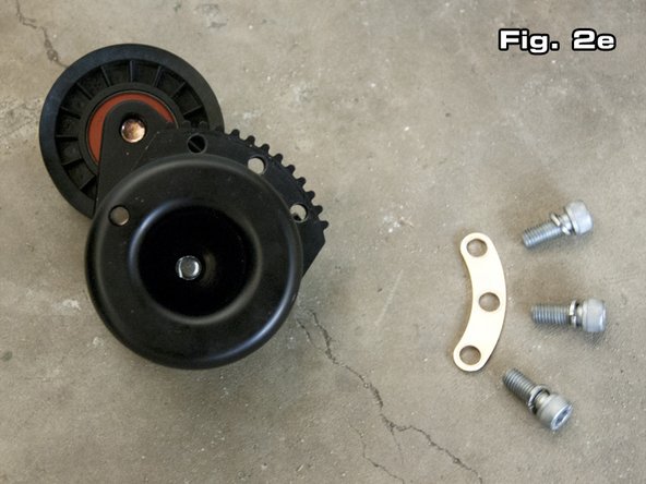
Figure 2e shows the parts that should be loose once the spring housing has been removed.
-
Shown from left to right is (1) spring housing, (1) bolt backing plate, and (3) M8 bolts and M8 lock washers. Torque all three M8 bolts to 35 lb-ft (dry) or 28 lb-ft (lubricated with oil). Failure to properly torque bolts can result in premature fatigue or loosening of the bolts
-
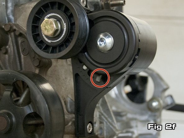
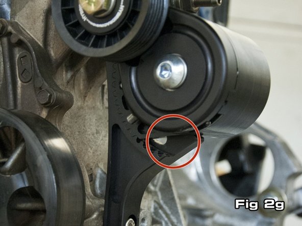
The autotensioner is supplied in its lowest position. Figure 2f shows how no open grooves are visible at the lower portion of the autotensioner. Figure 2g shows the autotensioner adjusted to its highest setting, where 4 grooves are showing. In the case of a k24, typically 2-3 grooves will need to show if the supplied belt is used.
-
In the case of a k20, typically 3-4 grooves will need to show if the supplied belt is used. The supplied belt is a 48.5” long 6-rib belt. Note that between the lowest and highest settings, there is enough adjustment to compensate for about a 2” variation in belt length. This allows some flexibility when it comes time to replace your belt.
-
-
-
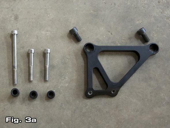
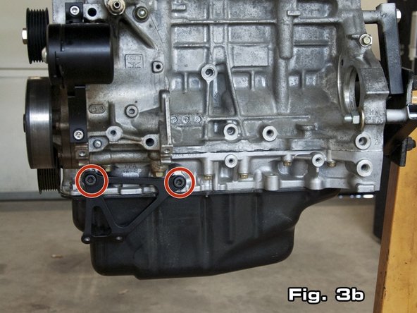
To reinstall the alternator, first the supplied alternator bracket (as shown on the right in Figure 3a) must be installed. The bracket bolts up to the same two (2) holes the original A/C bracket bolted to (see Figure 3b). Use the 2 supplied black M10x1.25 bolts.
-
The bolts can be tightened with an 8 mm or 5/16” allen driver. Do not fully tighten the M10 bolts until after the alternator has been installed. This will aid in properly aligning the lower two (2) holes in the alternator with the threaded holes in the alternator bracket.
-
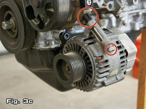
Once the alternator bracket has been bolted up, begin mounting the alternator by inserting the supplied 100 mm M8x1.25 bolt through the upper alternator mounting hole. Use n 6 mm allen wrench to tighten this bolt. This bolt should thread into the block where the top left mounting bolt for the A/C compressor originally went (as shown in Figure 3c).
-
-
-
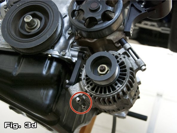
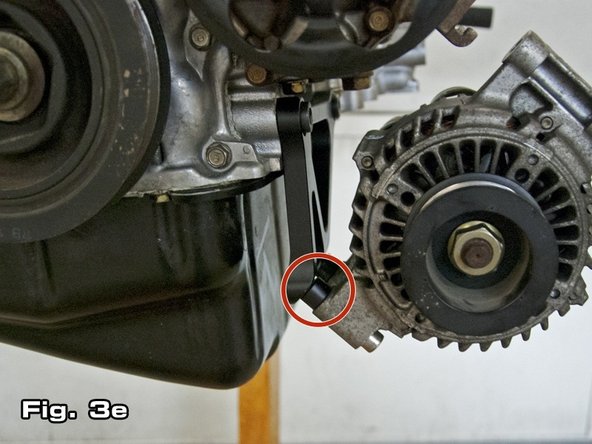
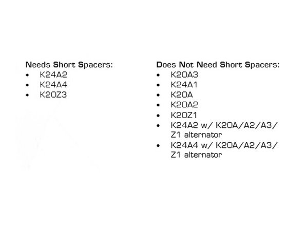
Next, affix the lower two (2) alternator mounting points to the alternator bracket as shown in Figure 3d. Some applications may require the use of the two (2) supplied short, black spacers between the alternator and bracket as shown in Figure 3e.
-
There are two (2) different flange thicknesses on K-series alternator for the lower two mounting bolts. If you have a 30 mm (1.18in) flange, use the supplied 55 mm M8x1.25 bolts. If you have a 40 mm (1.57in) flange, use the supplier 65 mm M8x1.25 bolts. See the table below to see if you should use them.
-
DO NOT use the lower spacers if your application does not require them.
-
-
-
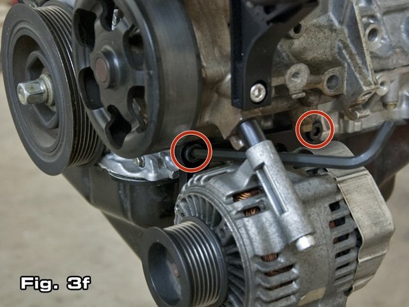
After all 3 alternator mounting bolts have been installed, first tighten all 3 alternator mounting bolts. Finally, tighten the 2 black alternator bracket mounting bolts. For best results, use a ballnose 8 mm or 5/16” allen wrench as shown in Figure 3f.
-
Torque all three M8 bolts to 35 lb-ft (dry) or 28 lb-ft (lubricated with oil). Torque both M10 bolts to 70 lb-ft (dry) or 55 lb-ft (lubricated with oil); a swivel joint is needed to access and properly torque these M10 bolts. Failure to properly torque bolts can result in premature fatigue or loosening of the bolts. (Note: color of bolts may vary)
-
The supplied tall black spacer should be fitted between the alternator and the engine block as shown in Figure 3c. Thread the bolt fully in but do not tighten until the lower two (2) bolts have also been installed.
-
-
-
Once the tensioner and alternator have been securely mounted, the supplied belt can be attached. The belt is most easily installed by first wrapping it around the crank, water pump, and tensioner pulley as shown in Figure 4a.
-
To install the belt onto the alternator, put a breaker bar with a 19mm (or 3/4”) socket on the bolt attaching the pulley to the autotensioner (see Figure 4a). In some cases, an open ended 19mm (or 3/4”) wrench may be preferred over a breaker bar. To rotate the pulley down, apply force to the breaker bar or wrench in a counter-clockwise direction.
-
With the pulley pivoted down, place the belt onto the alternator pulley. If the tensioner is adjusted such that belt is particularly tight, it may be necessary to install the belt onto the waterpump last, rather than the alternator.
-
-
-
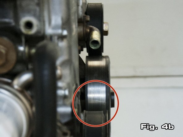
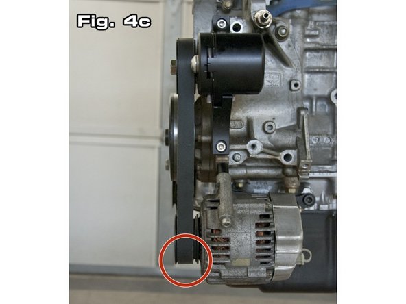
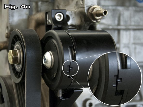
Because the alternator pulley is shifted back in its new location, the belt should wrap around the 6 ribs on the crank closest to the engine (see Figure 4bi and the 6-ribs on the alternator pulley furthest from the alternator (see Figure 4c).
-
Once the belt has been installed, check the tension indicator markings on the side of the autotensioner (as highlighted in Figure 4c). The small marking should fall inside of the larger marking if the belt is properly tensioned.
-
If you find that the belt is too short to be installed or that the belt is installed but is not properly tensioned as per the tension markings, this may indicate that the spring housing needs adjustment as discussed in Step 2. For best results, only use the tensioner after it has been calibrated so that the tension indicator markings are aligned.
-
Cancel: I did not complete this guide.
2 other people completed this guide.


