Introduction
What's included?
- x1 3" Hybrid Racing Silicone Cold Air Intake Tube
- x1 Velocity Stack Air Filter
- x1 Silicone upper radiator hose (for PRB style coolant neck)
- x1 Valve cover breather filter
- x1 Lower filter bracket
- x1 Anti-vibration clamp
- x1 Stainless T-bolt clamp
- x2 Silicone hoses for breather connections
- x2 Machined aluminum push-in fittings
- x5 Hose Clamps
- x2 Bolts
- x3 Washers
Fits:
02-06 Acura RSX / Honda Integra (without brake cooling ducts)
- Must use RBC intake manifold & big bore throttle body
- Modification to cars equipped with foglights may be required
01-05 Honda Civic Non-Si (K-Swapped)
- K-Series engine swap required
- Must use RBC intake manifold & big bore throttle body
- Modification to the lower bracket may be required
- Modification to cars equipped with foglights may be required
02-05 Honda Civic Si
- Must use RBC intake manifold & big bore throttle body
- Modification to the lower bracket may be required
- Modification to cars equipped with foglights may be required
-
-
Begin the installation by disconnecting and removing the battery and lower plastic tray.
-
If you have a relocated battery, simply disconnect it.
-
-
-
Unclip the battery wiring harness from the lower battery tray. Move it to the side.
-
Remove the Intake Air Temperature sensor from the intake system.
-
After removing the clamps and mounting bolts, remove the intake system completely.
-
This guide shows the removal of an aftermarket short ram intake. If you have the OEM air intake system, other parts may need to be removed that are now shown.
-
-
-
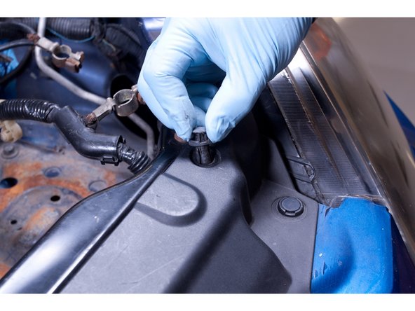
Remove the bumper. Start by removing all of the clips that hold the top section of the bumper and grille in place. There are 6 clips.
-
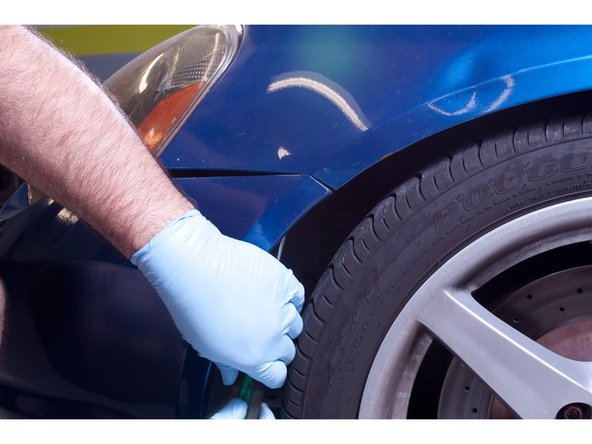
Remove the two bumper side mounting screws, as well as any screws or clips on the underside.
-
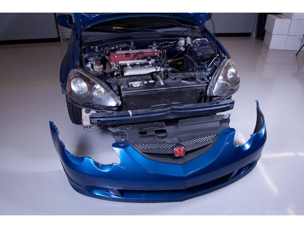
Remove the bumper cover and set it aside.
-
-
-
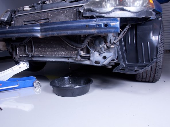
Find a suitable jack point and raise the car enough to slide a drain pan under the radiator.
-
Remove the radiator cap and drain roughly 1 quart of coolant. Drain just enough so you can remove the upper rad hose without making a mess in your engine bay.
-
Use a clean pan or tray if you plan to reuse the coolant.
-
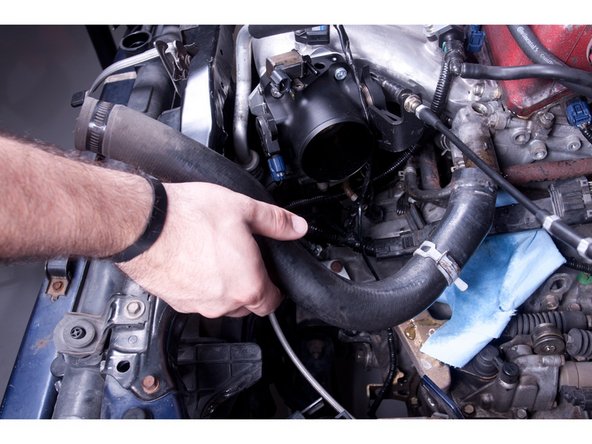
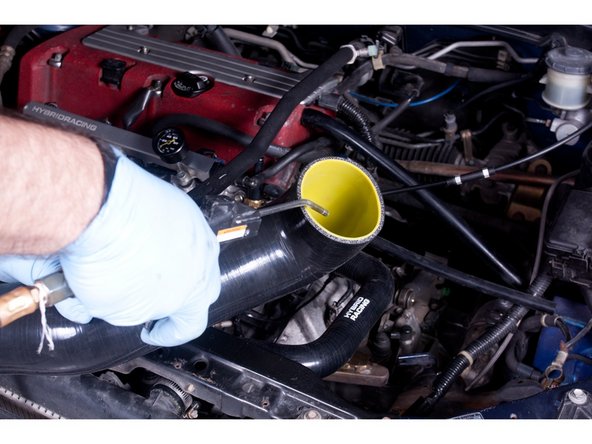
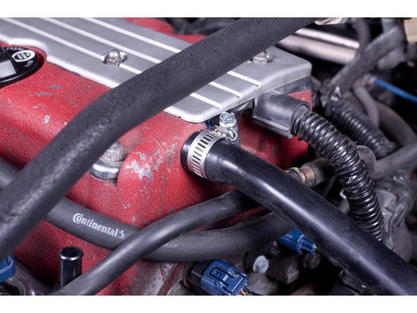
Remove the OR upper radiator hose.
-
Install the provided HR upper cooling hose. You can use the factory hose clamps, or replace them with our stainless T-bolt clamps. (sold separately)
-
-
-
The HR intake system requires the removal of the factory windshield washer reservoir. Remove all of those components now.
-
Relocation of the washer bottle system is possible, but it is up to you to determine how to do it.
-
Since the intake system locates the filter inside of the bumper, behind the bumper duct, this system may NOT be compatible with JDM ITR braking ducts. Due to the limited space, there is no room for all of it to fit.
-
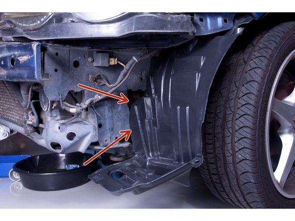
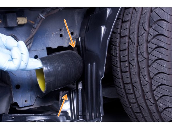
Install the HR silicone intake tube and mark out a section of the inner fender liner. Part of the liner will need to be cut in order for the liner to attach to the factory locations.
-
Confirm the liner can reattach with the intake system in place.
-
-
-
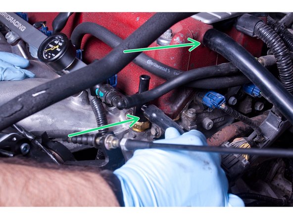
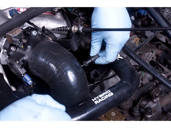
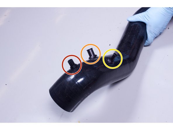
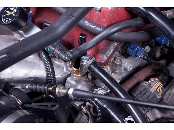
(Optional) If you want to install the Air Assist Valve tube, connect the supplied hose and route it to a spot on the intake tube. If you choose not to make this connection, DO NOT DRILL A HOLE FOR IT.
-
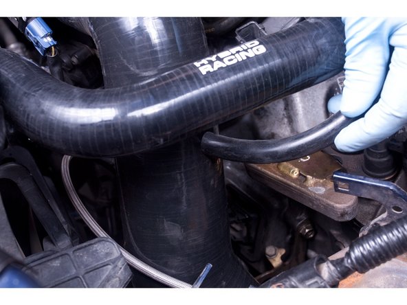
(Optional) If you want to install the valve cover breather tube, connect the supplied tube and route it to a spot on the intake tube. If you choose to NOT make this connection DO NOT DRILL A HOLE FOR IT and move to step 7.
-
The Air Assist Valve allows for a faster warm-up in cold weather. The cylinder head cover breather tube allows for pressure relief. This may allow oil vapor to be ingested into the engine. Consider connecting an oil catch can, or simply install a breather filter if you choose.
-
-
-
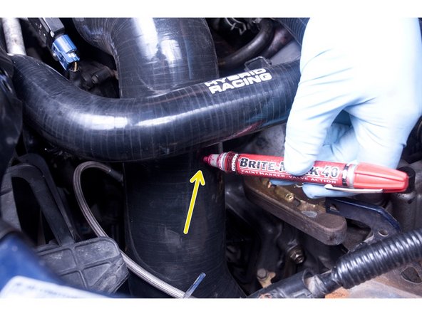
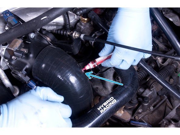
The Intake Air Temperature sensor is required for normal operation. You MUST mark and drill a hole in the tube. The location should be near the throttle body inlet for the most accurate reading.
-
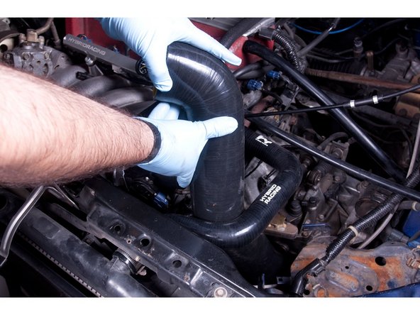
Once you have chosen and marked a location on the tube, remove it from the car.
-
-
-
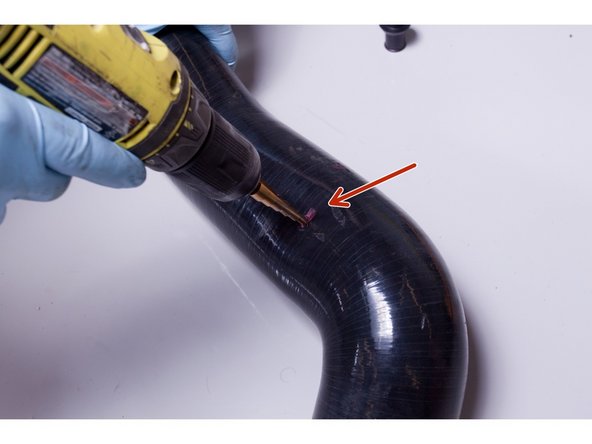
Using the supplied vacuum fittings as a guide, drill holes in the intake tube where you marked. Be sure to start with a smaller hole before going larger. It is always possible to enlarge a hole, it is impossible to make it smaller once it has been drilled.
-
The VC breather hose and AAV connections are optional. The IAT MUST be installed.
-
Be sure to CLEAN the air intake system before installing it. Compressed air works best.
-
-
-
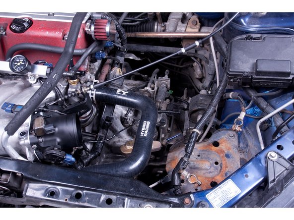
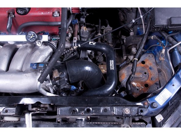
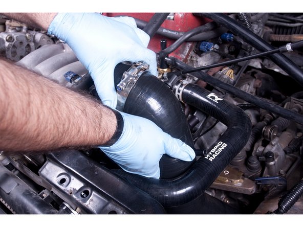
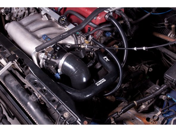
Install the intake tube for the last time.
-
If you are using the VC breather and AAV tubes, use and tighten the supplied hose clamps.
-
Plug the IAT sensor back in.
-
-
-
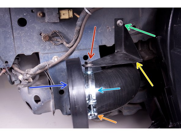
Using the supplied hardware, bolt the lower support bracket to frame rail.
-
Install the velocity stack and lower clamp mount and use the supplied bolt and tighten them together.
-
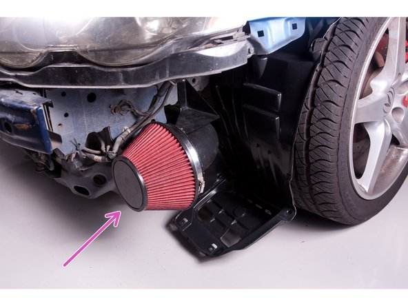
Install the high flow air filter and tighten all connections. Make sure the edge of the air filter does not contact the lower frame pinch weld.
-
Once all connections are tight, the intake system installation is complete. Re-install the front bumper & battery.
-
Fill the cooling system to capacity. You should not need to bleed the system as only a small amount of coolant should have been removed.
-
Due to the intake's high flow design, fine tuning of the fuel map may be required. Review your AFR (air fuel ratio) to insure optimal performance.
-