Introduction
HYB-SCA-01-43 Install Guide
-
-
Disconnect Batter Terminals
-
Remove GROUND Terminal first.
-
Use 10mm Deep-Socket to loosen x2 Nuts for batter Tie-Down
-
-
-
Remove Positive terminal cable from its mounts on Battery Tray.
-
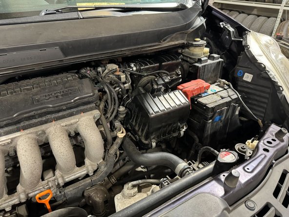
Remove Battery
-
-
-
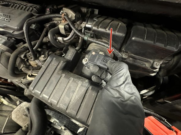
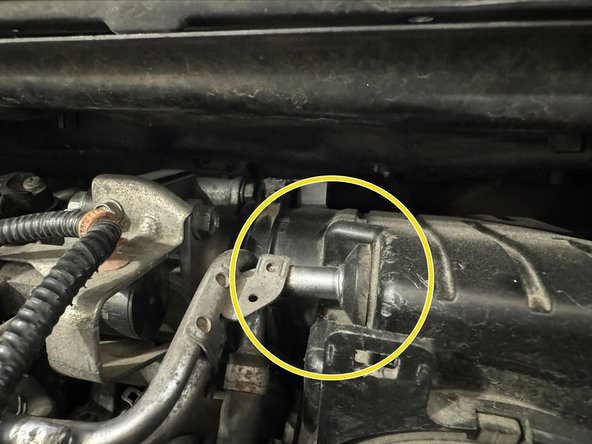
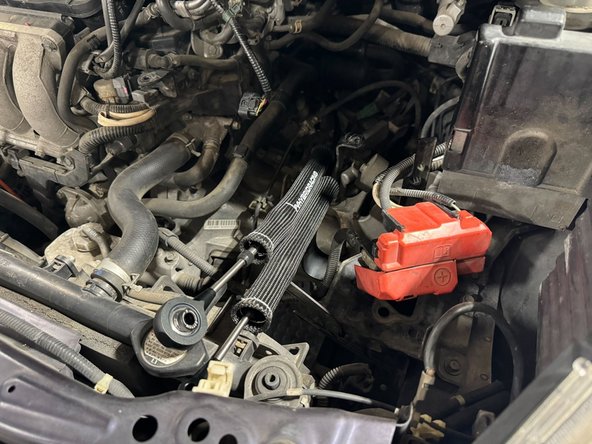
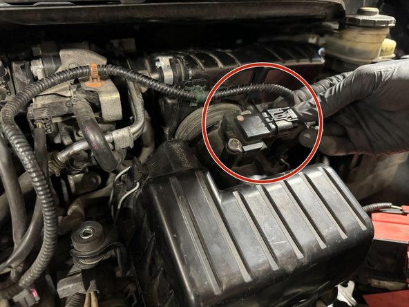
Unplug MAF connector. Release latch on connector by pushing down on the tab.
-
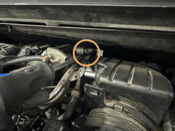
Using 5.5mm Socket or Philips Driver, loosen Throttle-Body clamp.
-
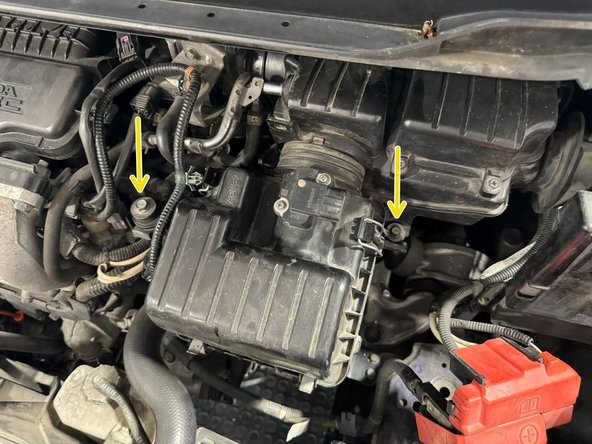
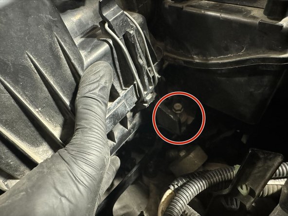
Using 10mm Socket, remove the x2 intake box mount bolts
-
-
-
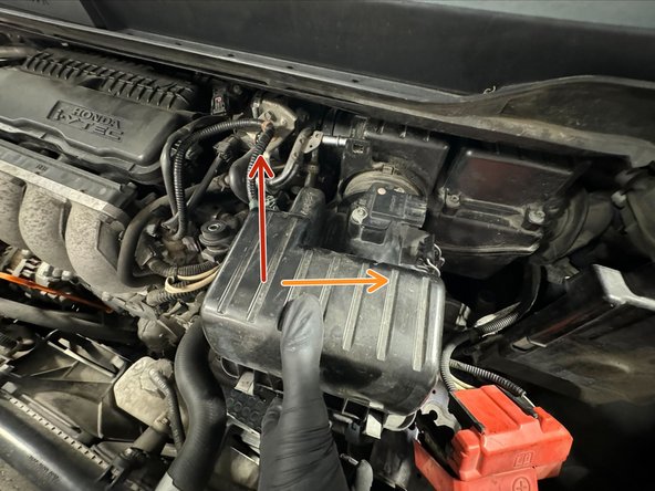
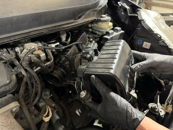
Rotate front of Intake-Box upwards.
-
Then lightly pull towards drivers side (US).
-
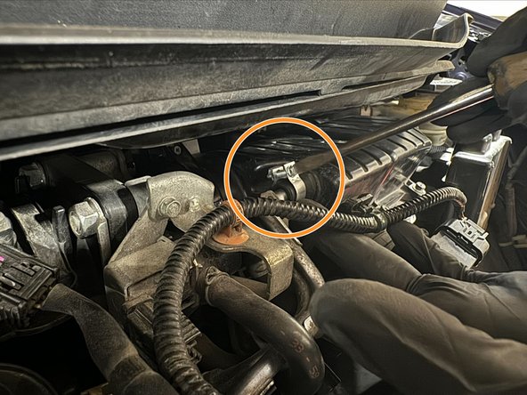
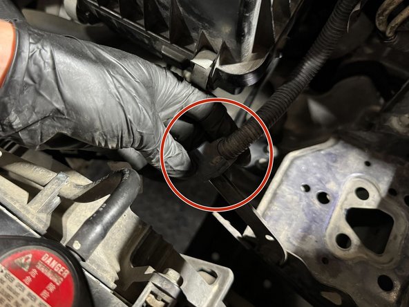
Reach behind the Intake-Box and pull it off of the Throttle-Body
-
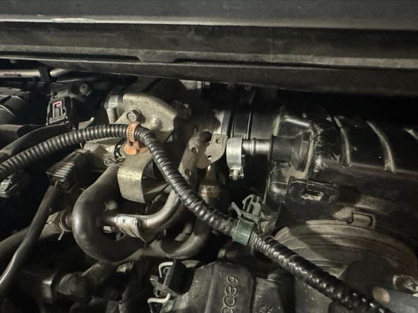
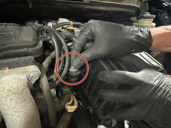
Remove clamp and pull metal PCV tube out of grommet.
-
Grommet on vehicle used to make this Guide is broken and no longer had clamp.
-
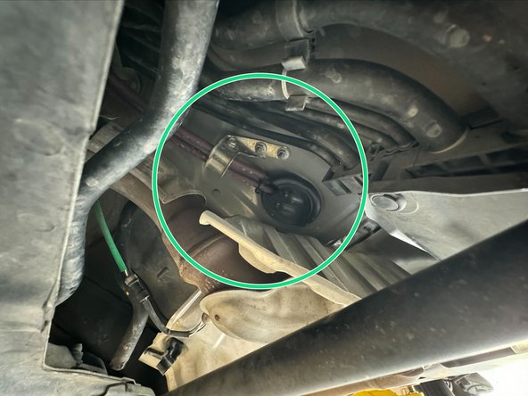
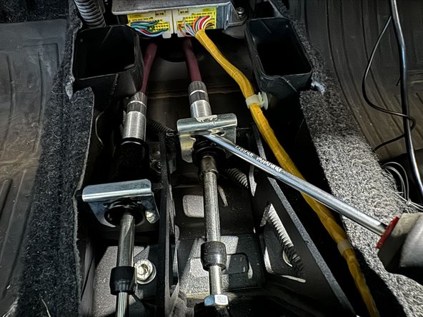
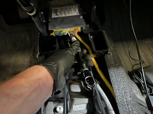
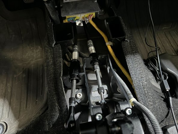
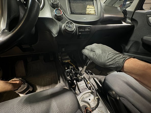
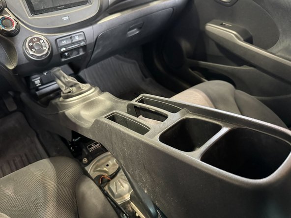
After Intake-Box removed, the top of Transmission and the Shifter Cables will be exposed
-
-
-
Cables removed from the vehicle in this guide are not OE. But the removal procedure is the same.
-
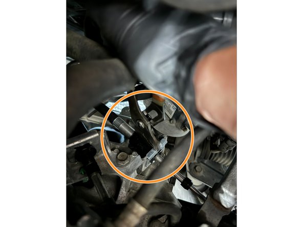
Remove the Shifter Cable Clips. Use a Channel-Lock pliers and/or Flat-Head Driver to remove the clips.
-
Flat-Head Drive shown in first image, Channel-Lock in second image.
-
The Cable Clips are most tedious part of removal and install! On older vehicles, it can take a lot of force to remove.
-
-
-
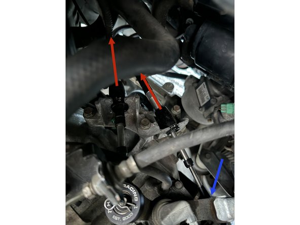
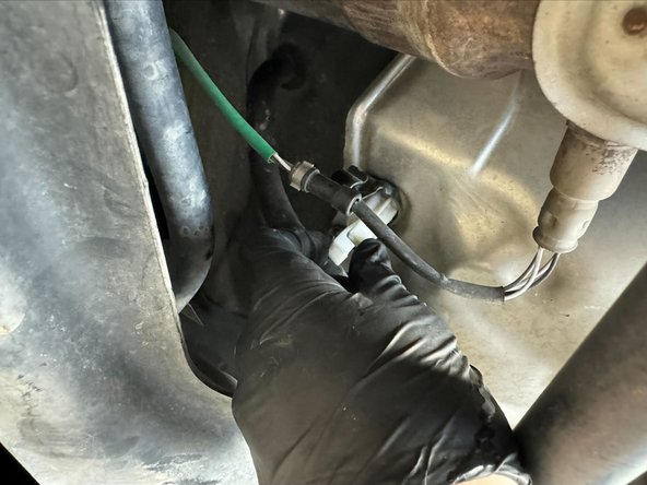
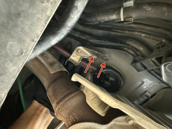
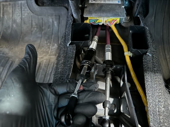
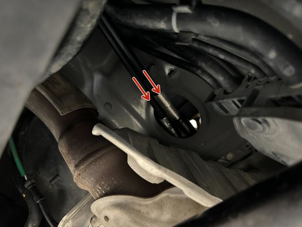
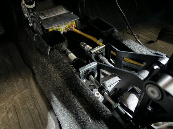
Push the cables (in direction of arrows) into the exhuast tunnel to disconnect them from the bracket.
-
Once removed from the bracket you are now free to remove the cables from the pins. Its important that you do this step first in order to allow for this endlink to slide off of the pin without damaging it.
-
-
-
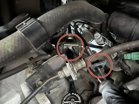
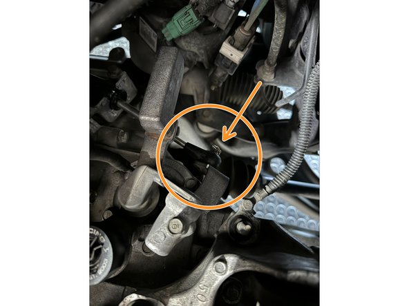
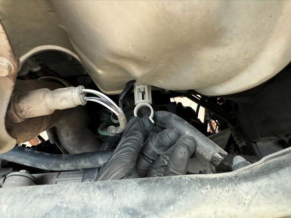
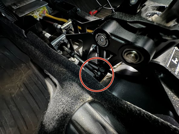
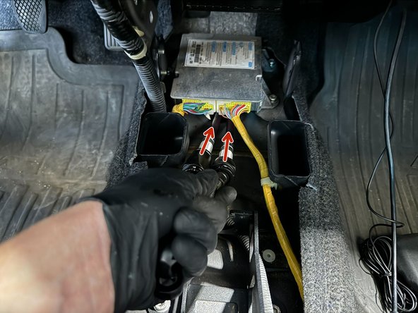
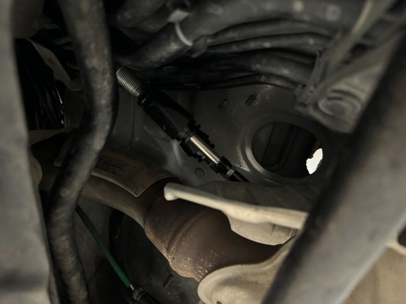
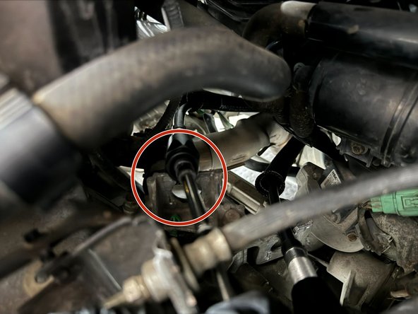
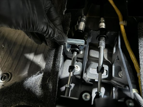
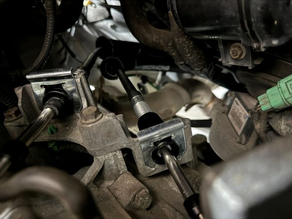
Remove the Cotter-Pin from cable on top of Transmission and slide the endlink off.
-
This is the Front-Back cable. It transmits the Front-Back action of the shifter to the transmission.
-
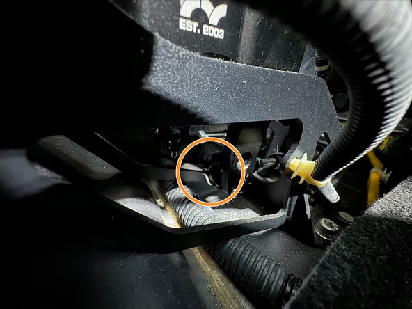
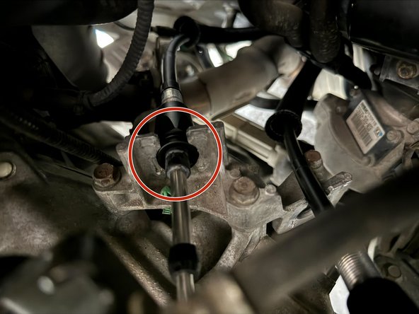
Remove the Cotter-Pin from the cable on backside of Transmission and slide the endlink off.
-
This is the Left-Right cable. It transmits the Left-Right action of the shifter to the transmission.
-
-
-
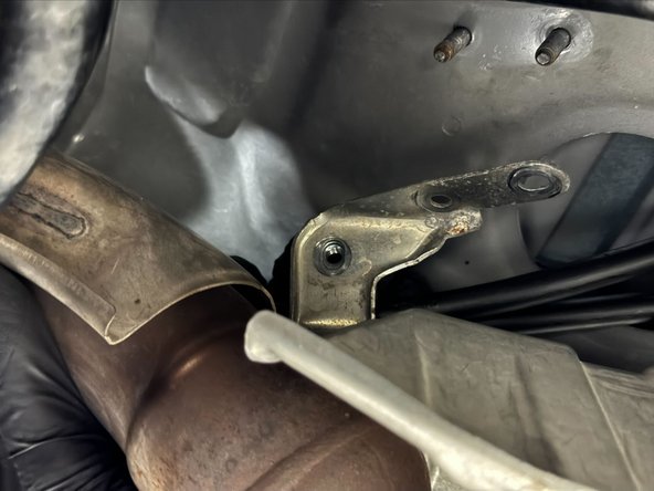
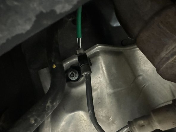
Unclip A/C Condenser drain from stand-off mount
-
Unclip Oxygen sensor from black metal stand-off mount
-
Unscrew the white plastic A/C Condenser stand-off mount. This will expose x1 of the x3 nuts holding Heat-Shield.
-
-
-
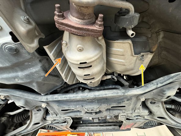
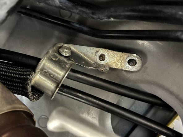
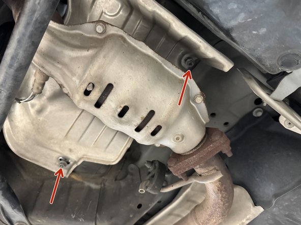
Use 10mm Socket to remove x3 Nuts holding Heat-Shield to Chassis.
-
x1 Under A/C Drain stand-off
-
x1 On drivers side (US) of CAT (hidden above CAT in image)
-
x1 On passengers side (US) of CAT
-
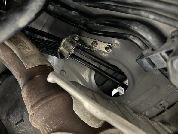
Move Heat-Shield to expose Shifter Cable Mount and Chassis Grommet
-
-
-
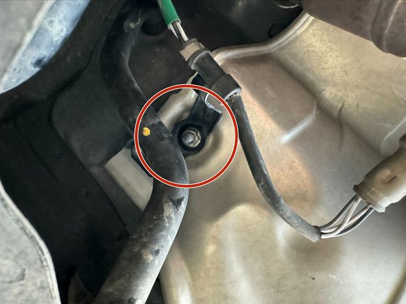
Use 10mm Socket to remove x2 Nuts from Shifter Cable Mount
-
Pull down on mount to remove from studs
-
-
-
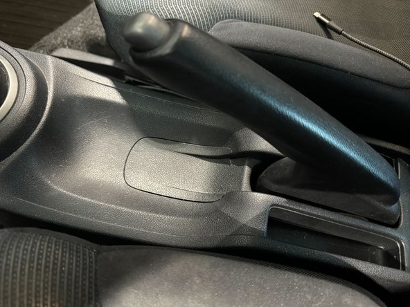
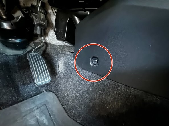
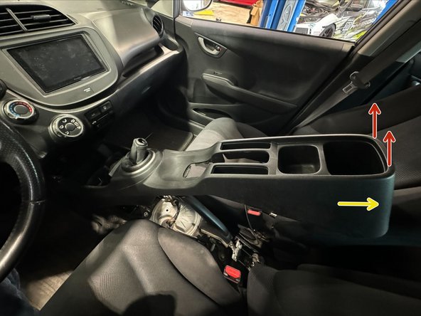
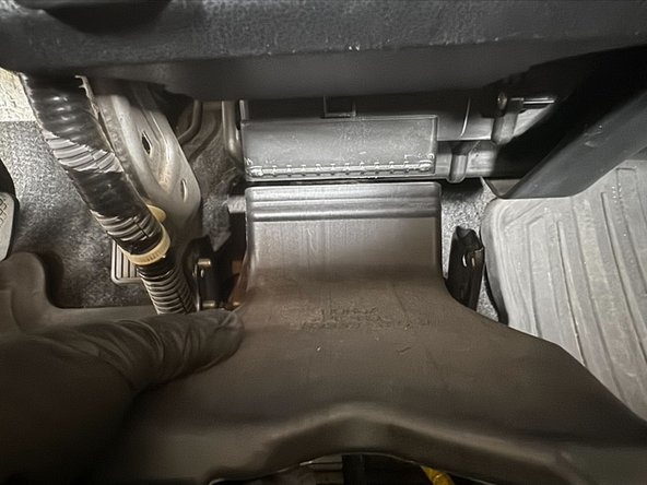
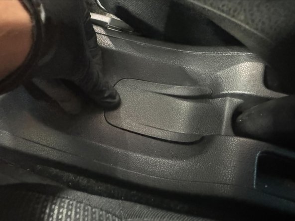
Pull up on the small panel underneath the handbrake.
-
Remove this panel will console to slip over the handbrake
-
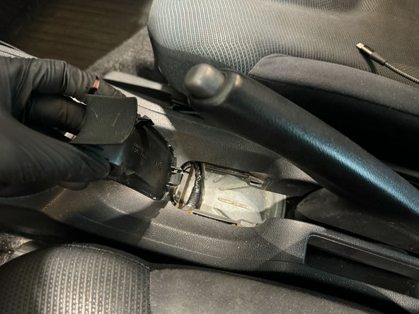
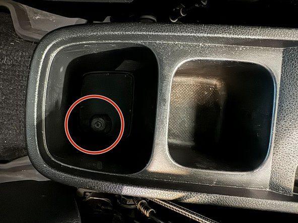
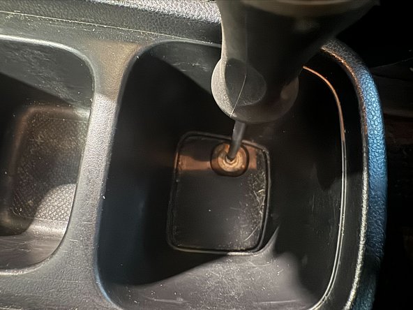
Use a Philips-Driver to remove the bolt in rear cavity of console.
-
-
-
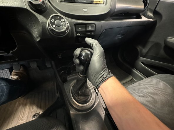
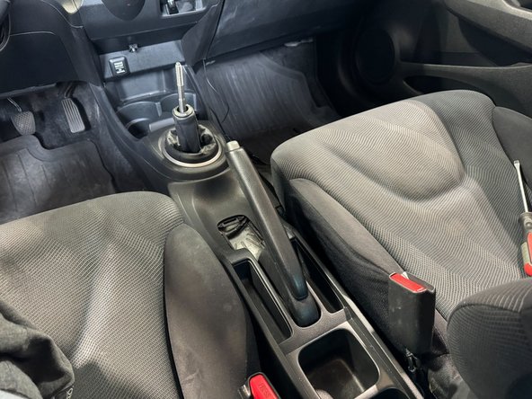
Remove shift knob.
-
Do NOT need to remove boot
-
Remove the x2 Panel-Clips in drivers and passengers foot-wells
-
-
-
Pull UP at rear of console.
-
Once it is above handbrake, pull backwards towards the rear seats.
-
-
-
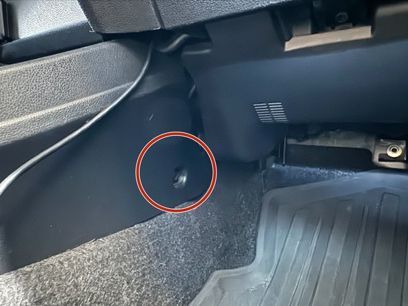
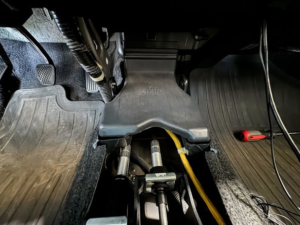
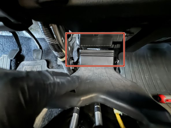
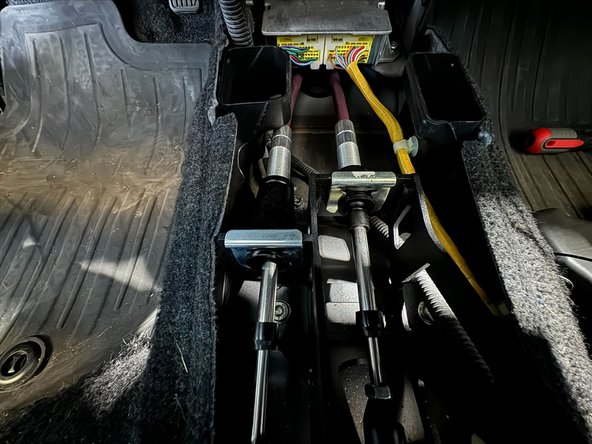
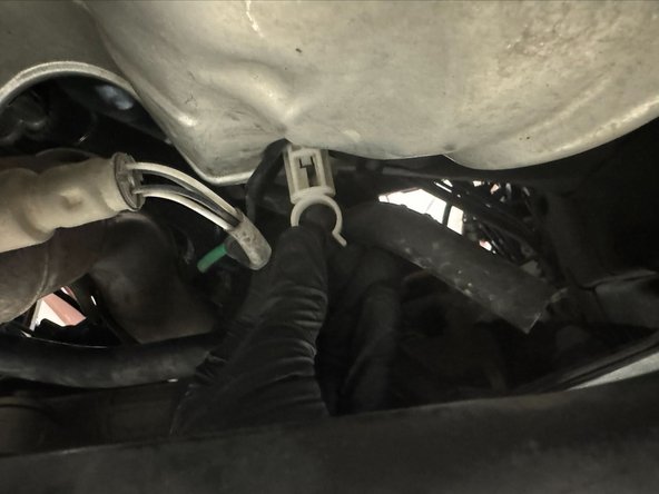
After removing the console, remove the A/C duct. This will give you a better line-of-sight to the cable chassis grommet.
-
Pull down on the slip fit connection to disconnect.
-
-
-
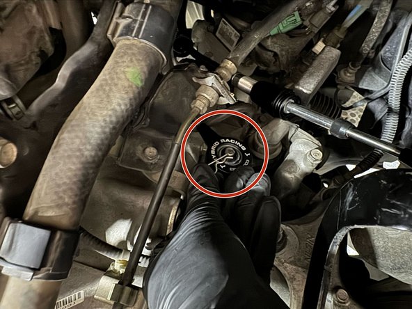
Vehicle used to make this guide had Hybrid Racing Short Shifter installed. Procedure to remove cables will be the same with OE shifter.
-
Remove the shifter cable clips. Use same technique as removal from the Transmission.
-
Remove cotter-pin holding Left-Right cable to shifter.
-
Spread retaining clip on Front-Back cable. Then push the cable end-link towards drivers side (US).
-
-
-
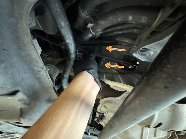
After cables disconnected from shifter, push cables into the Exhaust-Tunnel. This will also pop the Chassis Grommet loose.
-
Front underneath the vehicle, pull/push cables out of the vehicle.
-
The bushings, endlinks and brackets on cables easily get caught on shifter, wiring and plumbing.
-
It will take several iterations of moving between interior, engine bay, and underneath vehicle to free the cables. This is a tedious step.
-
-
-
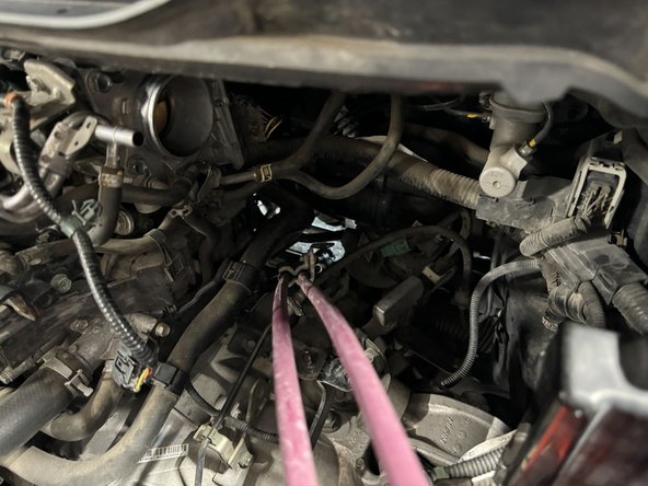
After cables are free interior, pull them out through top of engine bay.
-
Hybrid Racing Shifter Cables will be installed in reverse order of these steps.
-
-
-
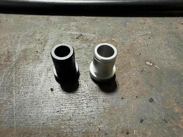
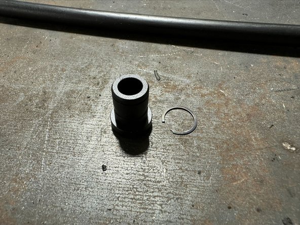
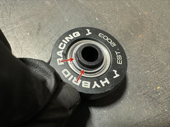
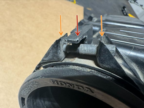
Cables are supplied with x2 inserts. The inserts are different inner diameters. Use the Black insert on 09-14 Fits.
-
Put insert into spherical bearing on FB cable. Use supplied retaining ring to lock insert in place.
-
DOUBLE CHECK that retaining ring is fully seated into groove on insert.
-
-
-
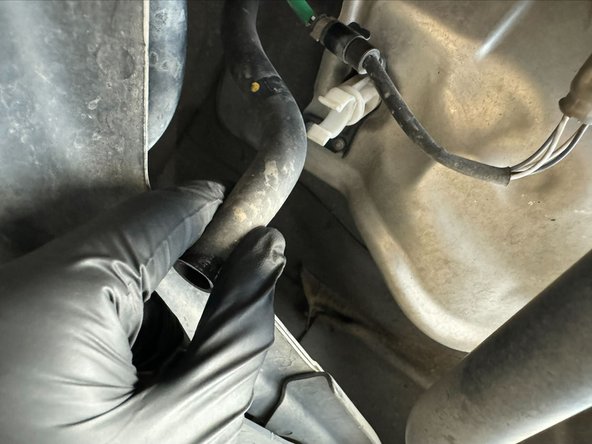
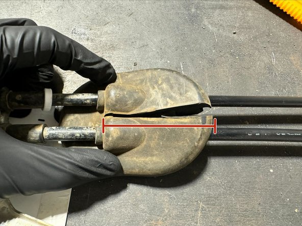
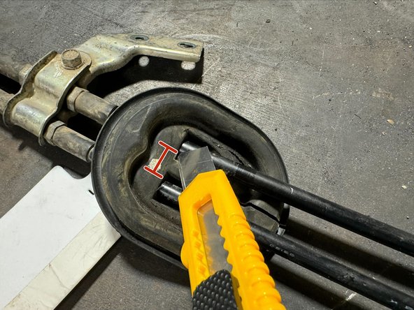
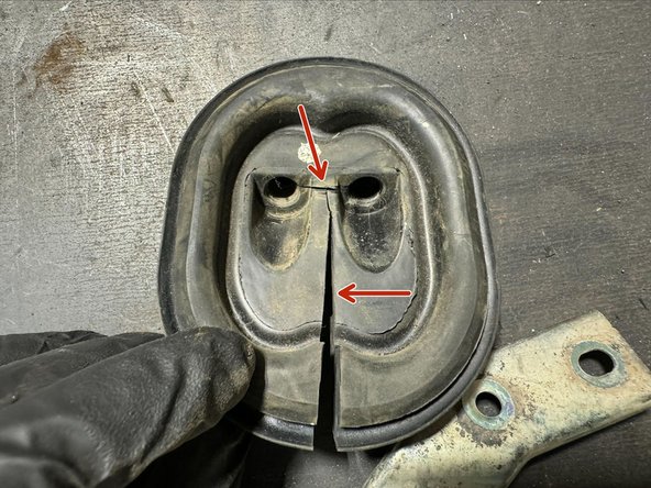
The Chassis seal will need to be harvested from OE cables.
-
Using a sharp blade, cut through seal as shown in pictures.
-
If cut differently from shown in guide, it can be much more difficult to reinstall with Hybrid Racing Shifter Cables.
-
Cables shown in these 3 images are 07-08 Fit cables. Grommet is almost identical to 9-14 Fit (we did not have set of uncut OE 9-14 Fit cables on-hand during making of this guide)
-
-
-
Remove the mounting bracket from OE cables. Use a 10mm socket to remove bolt.
-
Bend bracket open so that there is large enough gap to remove OE cables.
-
DO NOT install on Hybrid Racing Cables until cables are positioned in car.
-
-
-
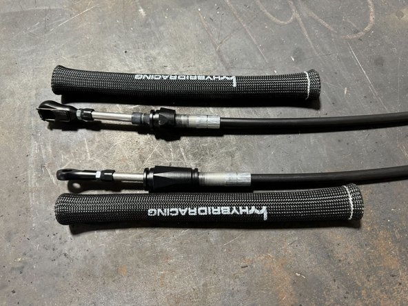
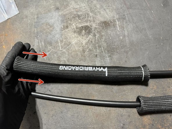
From the shifter side of Cables, push the fiberglass heat sleave on to cables.
-
Push all the way to transmission side of Cables.
-
Tip: push over the cable bracket mounting bushings. This will hold heat-sleave in place while feeding cables through engine bay. (See 3rd image)
-
-
-
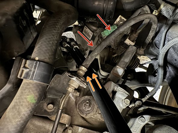
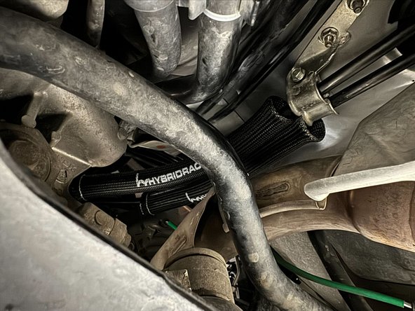
Pass the shifter end of cables underneath the clutch line.
-
Route cables along side of exhaust.
-
Once cables are not hanging out of engine bay, move to underside of car to feed cables into cabin from the exhaust tunnel.
-
-
-
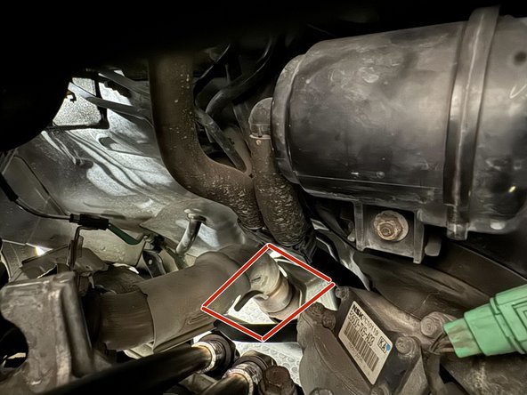
From underneath the car, push/pull cables into the cabin.
-
Once cables are inside cabin, move to interior to pull through.
-
-
-
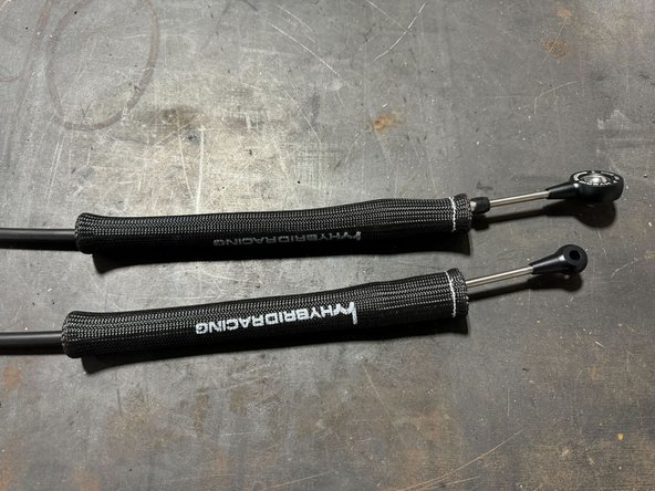
Pull cables further into cabin.
-
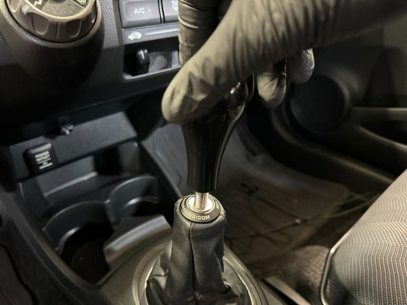
Put cables into there position on shifter (See 2nd image).
-
DO NOT mount cables to shifter or connect endlinks to shifter, yet. You will need compliance in the cables to mount bracket to chassis and install exhaust tunnel grommet.
-
-
-
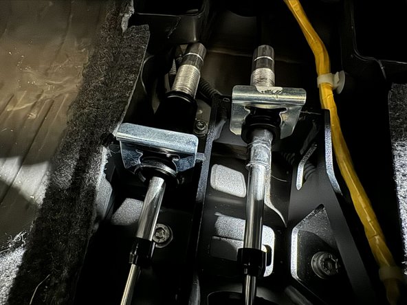
Place FB cable bushing in transmission bracket.
-
Place FB endlink on gear selector pin and retain using supplier cotter-pin
-
Repeat the same procedure for LR cable.
-
-
-
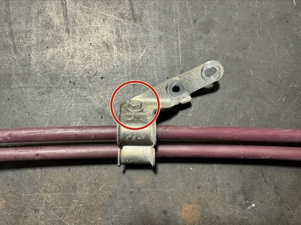
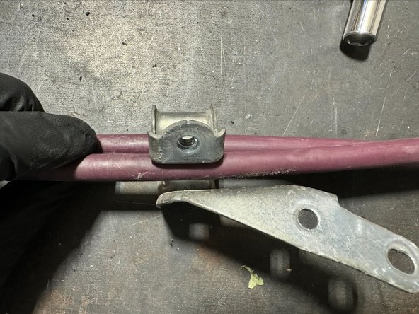
Slide cable bracket from OE cables onto Hybrid Racing Cables.
-
Squeeze bracket closed so that the 10mm bolt can be reinstalled.
-
Tighten 10mm bolt, the push bracket onto studs.
-
-
-
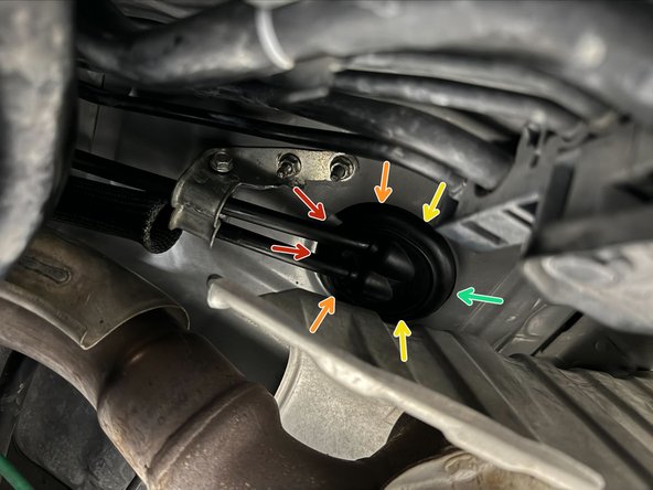
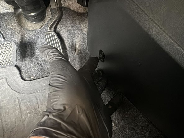
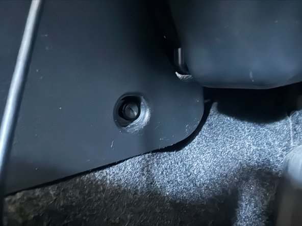
Put grommet onto cables.
-
Then push grommet into place. Clip the front of grommet into place first, then work the grommet into place from front to back.
-
Using reference arrows, start at Red, then move to Orange -> Yellow -> Green
-
-
-
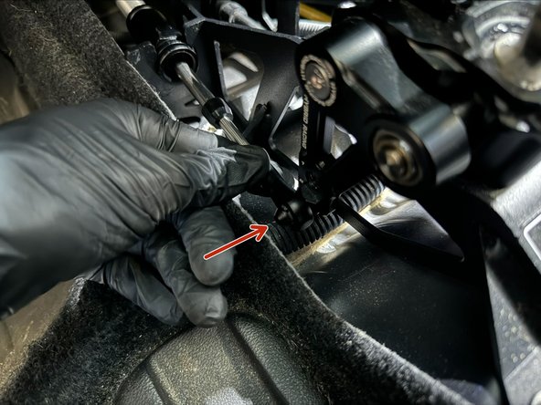
Push LR cable endlink onto shifter pin.
-
Use supplied cotter-pin to retain cable.
-
Clip FB cable endlink onto shifter pin.
-
-
-
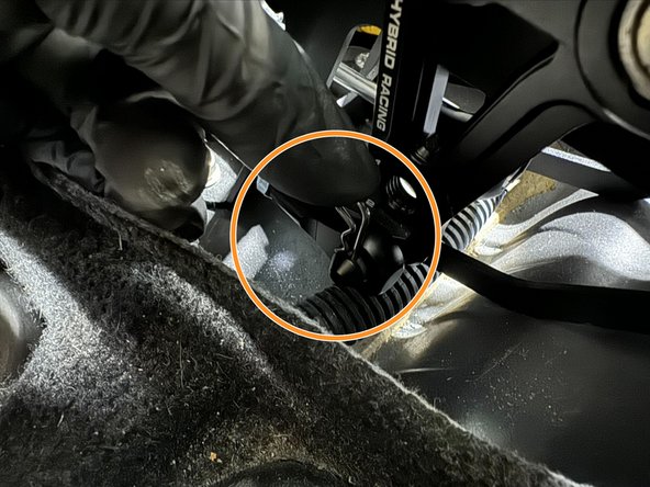
By hand, push cable clips into place.
-
Do not push cable clips all the way into place, yet. Before fully installing, need to first check that car can get into all gears.
-
-
-
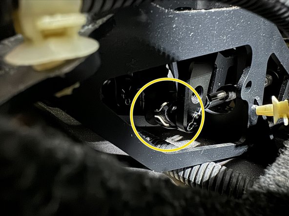
By hand, push cable clips into place.
-
Do not push cable clips all the way into place, yet. Before fully installing, need to first check that car can get into all gears.
-
-
-
Check that car can be put into all forward gears, and reverse.
-
If successful, move to next steps.
-
-
-
Using a 5lb hammer, tap the cable clips into place on both shifter and transmission.
-
Tip: the impact force from small swings of 5lb hammer is enough to push clips into place. Excessive force is not needed.
-
-
-
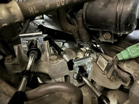
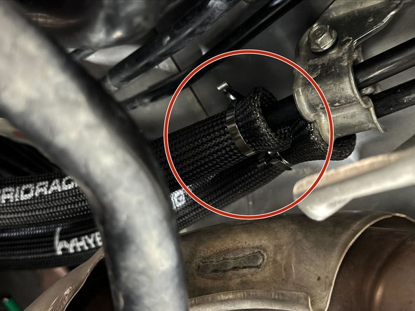
Pull heat sleeve down cables until it touches exhaust tunnel bracket.
-
Use the supplied Stainless steel ties to pinch heat sleeve only shifter cables.
-
Tip: We recommend neatly bending the extra length of SS ties after tightening. This will prevent a sharp edge from cutting/snipping.
-
-
-
Place heat shield over the x3 studs.
-
Clip oxygen sensor wires to black metal bracket.
-
The then tighten 10mm nut onto stud.
-
Twist on the white plastic stand-off for A/C condenser drain. Then clip condenser drain into place.
-
-
-
Complete heat shield install by tightening remaining x2 10mm nuts.
-
-
-
Double check that throttle body clamp is correctly positioned.
-
Route intake into place by pushing air-duct behind ECU.
-
Then push into position and mount to throttle body.
-
-
-
Tighten the x2 10mm bolts. This step completes the intake install.
-
-
-
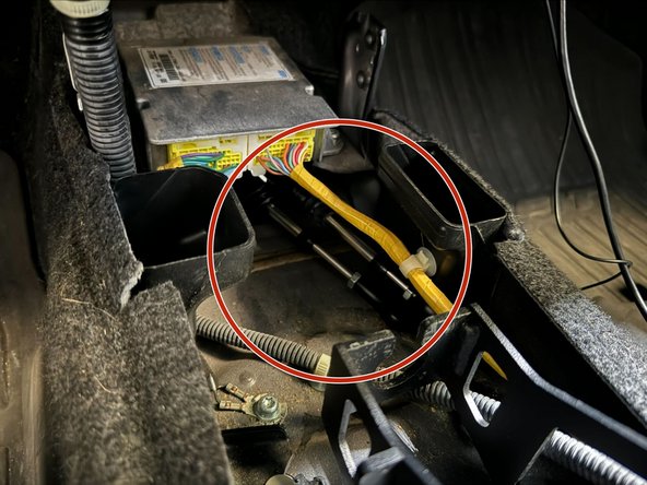
Reconnect the starter wire harness to its mounting tab
-
The reinstall battery tray and batter.
-
Tip: After battery in reinstalled, we recommend test driving the car before reinstalling the center console.
-
-
-
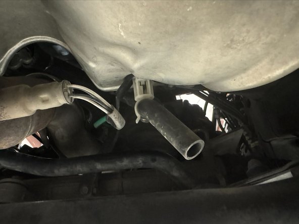
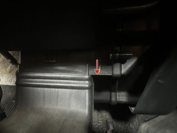
Reinstall the HVAC duct. Push up until the top of duct is level highlighted part of dashboard (Red Arrow)
-
-
-
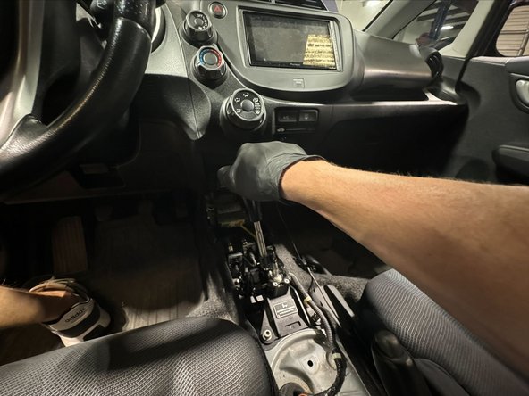
With rear of center console raised, push console into place in foot wells.
-
Lower the console and feed the shifter rod through shift boot.
-
Clip the hand brake cover into place.
-
-
-
Tighten the bolt in rear cavity of console.
-
Then install panel clips in driver and passenger footwells .
-
-
-
Last step is to install shift knob and boot collar.
-
This vehicle had Hybrid Racing Boot Collar and Delrin Shift Knob installed.
-