Introduction
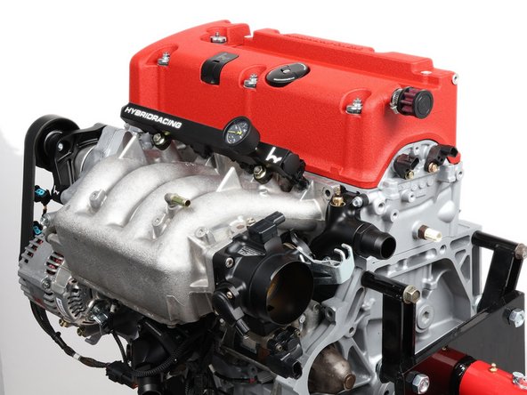
How to install the Hybrid Racing tucked engine harness on a non-drive-by-wire K-series swap. Most of the work is plugging in labeled connectors by hand. A K24-style crank or knock sensor needs one terminal moved. GND and the two heavy cables bolt down; OIL and ST push on. The ground kit and conversion harness follow their own instructions.
Tools
-
-
Disconnect the battery first, before you unplug or remove anything, and leave it disconnected until the entire install is finished.
-
This harness is for a non-drive-by-wire K-series running an RSX Type-S (PRB) ECU or K-Pro. It is not for the 2005-2006 RSX drive-by-wire setup.
-
It comes prewired for the common K20A2 (RSX Type-S) style sensors. What matters is the sensor on your engine, not the engine's name. Replacement K24 crank and knock connector housings are included in the kit.
-
You still need a ground kit, an ECU, and, depending on your swap, a conversion harness. Those are separate items. The immobilizer is handled at the ECU, not on this harness.
-
Remove the old harness so every sensor you will plug into is bare and unplugged, and pick your ECU mounting spot before you start.
-
This product may not be legal for highway use. Check your local emissions rules.
-
The photos show the harness going onto an engine out of the car. The connector work is the same either way; the firewall and ECU work in Step 11 happens with the engine in the chassis.
-
-
-
In the box: the main harness, the injector sub-harness, the VSS sub-harness, replacement K24 crank and knock connector housings, two heavy power cables, and zip ties (push mount and regular). The three spare wires come built into the main harness.
-
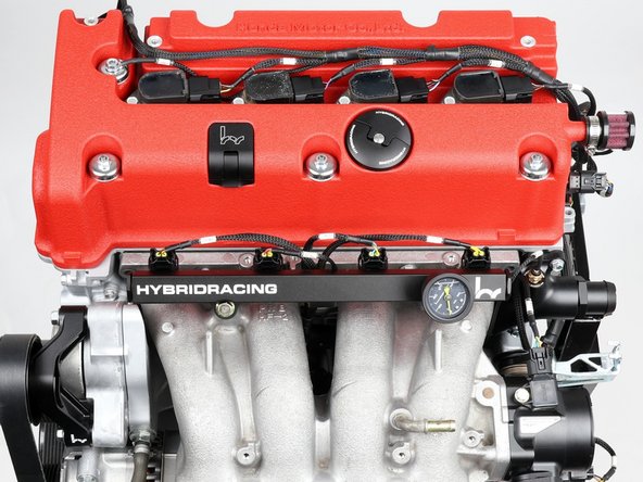
Set the long cabin section, the run that ends at the ECU, on the cowl, out of the way, and lay each branch into its area of the engine before you plug anything in. The photos show the harness fully routed for reference; some connectors are held just off their sensors.
-
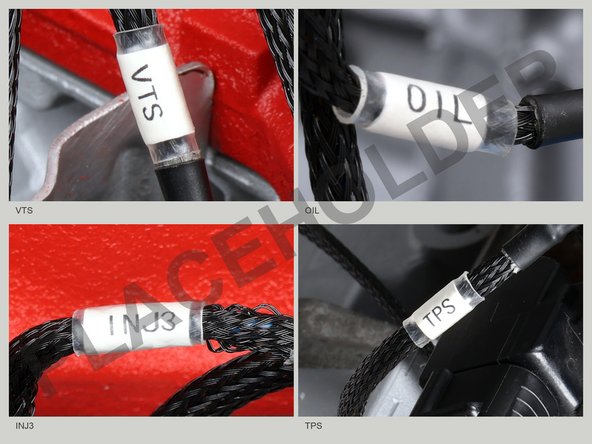
Every branch wears a printed label (VTS, OIL, INJ3, TPS, and so on). If you are not sure what something is, read the label.
-
The chain side is the end with the crank pulley and accessory belt. The far end, where the transmission bolts on, is the transmission side. The steps below use those two names.
-
Some branches carry extra length on purpose. The harness fits both the K20 and the taller-deck K24, so any branch whose sensor moves between the two engines is cut long by design.
-
The color word at the front of a bullet is the color of the ring drawn around that connector in the step photo. It is not the wire color.
-
Every click-in connector seats by hand. If a plug does not fit, stop and check the printed label, the orientation, the seal, and the terminals. Never force or modify a connector.
-
-
-
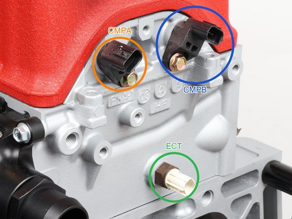
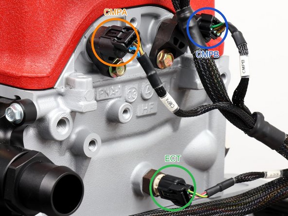
Plug in the engine coolant temperature sensor (labeled ECT, green ring) low on the end face of the head at the transmission end. This is the ECU's temperature feed; the dash gauge wire (H20) is a separate circuit in Step 7.
-
Plug in cam sensor A (labeled CMPA, orange ring) on that same end face, tucked up under the valve cover lip.
-
Plug in cam sensor B (labeled CMPB, blue ring) on the same face. Facing that end face the way the step photos are shot, CMPB sits above and to the right of CMPA.
-
CMPA and CMPB look alike and sit close together. Swapping them is a common cause of a no-start. Match each label before you connect.
-
Depending on your head, the ECT and cam sensors sit in slightly different positions. Go by the labels; the branches have the length to reach.
-
-
-
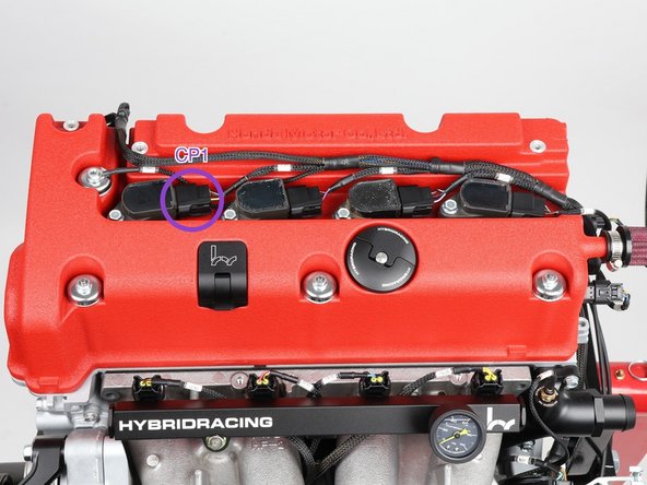
Lay the coil sub-harness across the valve cover and plug in the four coils in order, CP1 through CP4 from the chain side (the violet ring marks CP1).
-
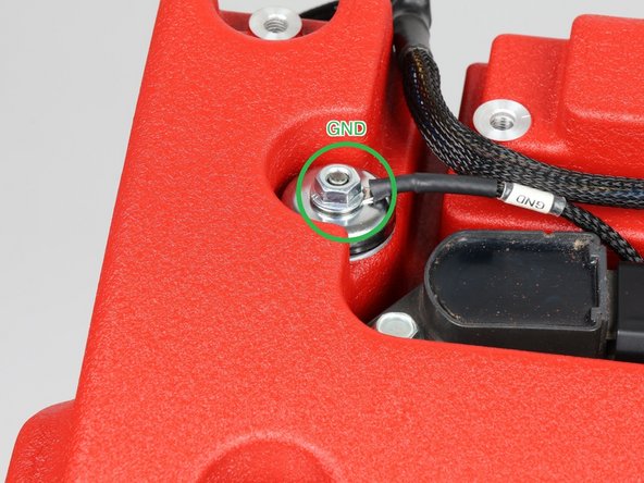
Land the ground eyelet (labeled GND, green ring) on the valve cover stud. The stud must be clean bare metal and the nut tightened down. A loose or painted-over ground causes strange problems that are hard to chase.
-
This is the only ground on the harness. Install the main power grounds now from the ground kit (sold separately), transmission to chassis and battery to chassis, per its included instructions. A missing main ground causes hard to chase electrical problems.
-
-
-
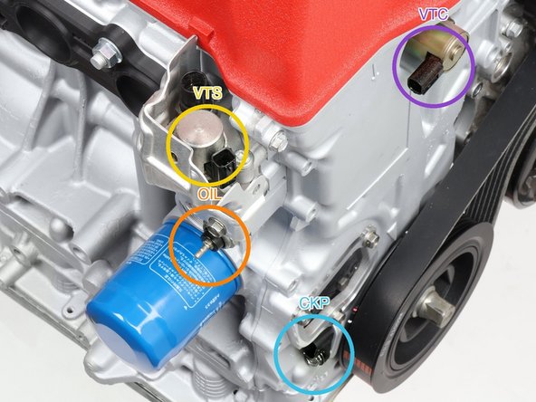
Plug in the VTEC solenoid valve (labeled VTS, yellow ring) on the side of the head above the oil filter.
-
Connect the single OIL wire (labeled OIL, orange ring) to the engine oil pressure switch just above the oil filter. This one is a push-on terminal under a rubber boot, not a click-in plug.
-
Plug in the VTC oil control solenoid (labeled VTC, violet ring) up by the valve cover.
-
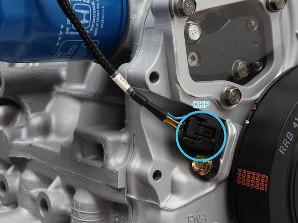
K20 sensor (37500-PNB-003): plug the CKP connector (labeled CKP, light blue ring) straight in at the crank pulley. K24 sensor (37500-RAA-A01): move the three terminals into the included replacement K24 housing first, then plug it in.
-
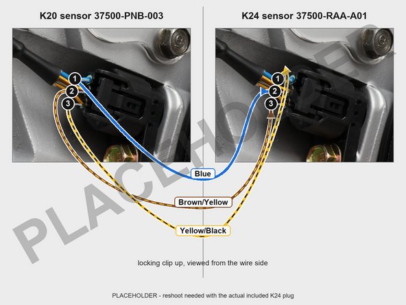
Honda pin numbers: hold each connector with its locking clip facing up and look at it from the wire side. Both plugs are numbered that way below.
-
K24 terminal move: pull the internal lock on the harness CKP plug with a pick and slide the three terminals out the back. Blue goes from old pin 1 into new pin 2, Brown/Yellow 2 into 3, Yellow/Black 3 into 1. Seat each until it clicks, tug to confirm, then push the lock back in and check that every terminal sits flush at the mating face.
-
Confirm each wire color before you move it. A miswired crank sensor means a no-start.
-
The harness has no plug for the VTEC oil pressure switch, so that switch stays unplugged; that is intended. If you run K-Pro, disable that input in your tune or it can set a code.
-
-
-
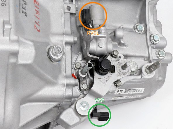
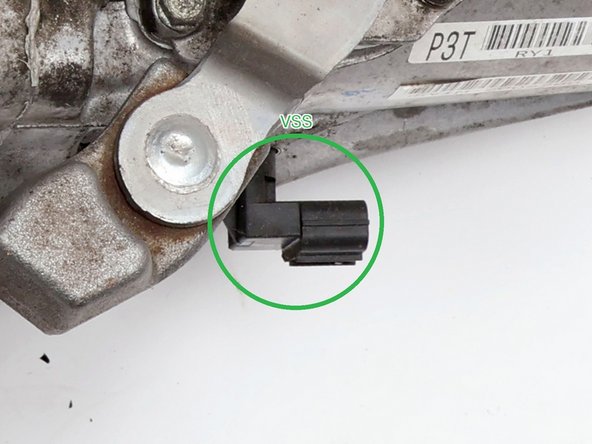
Connect the included VSS sub-harness to the transmission speed sensor connection: on the K20 final-drive VSS that is an in-line connector clipped into a bracket at the lower edge of the case, not a plug on the sensor body (VSS ring, shown close up in the third photo). Tie the sub-harness up so it cannot hang loose.
-
Plug in the reverse lockout solenoid (labeled RVSL, orange ring).
-
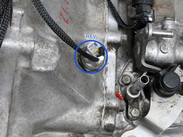
Plug in the back-up light switch (labeled REV, blue ring).
-
If your transmission uses a countershaft-driven speed sensor instead, that is what the plug labeled VSS2 is for. A Z3-style adapter is available to match it, with no rewiring.
-
Connectors your setup does not use stay capped and get zip tied out of the way, off the exhaust and away from moving parts.
-
-
-
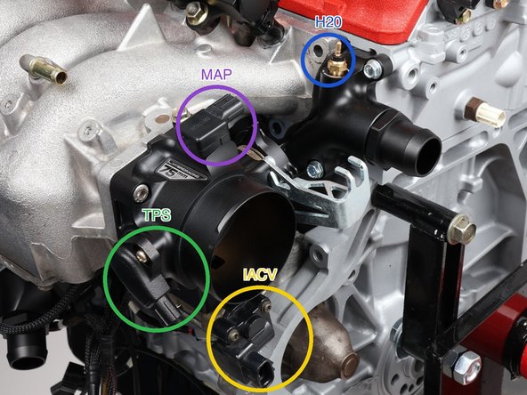
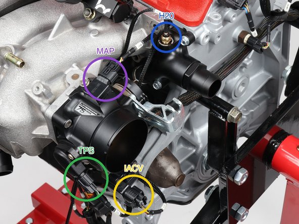
Plug in the throttle position sensor (labeled TPS, green ring) on the side of the throttle body.
-
Plug in the idle air control valve (labeled IACV, yellow ring) just below the throttle body.
-
Plug in the MAP sensor (labeled MAP, violet ring) on the manifold flange behind the throttle body.
-
Connect the coolant temp gauge wire (labeled H20, blue ring) at the water neck. This wire feeds the dash temperature gauge, not the ECU. The ECU gets its reading from ECT in Step 3.
-
Plug in the intake air temperature sensor (labeled IAT). It lives in the intake duct, not on the engine, so leave this branch loose until your intake is on.
-
This harness carries no EVAP purge or oxygen sensor connector. That is intended. Both are handled outside this harness, on the conversion harness side.
-
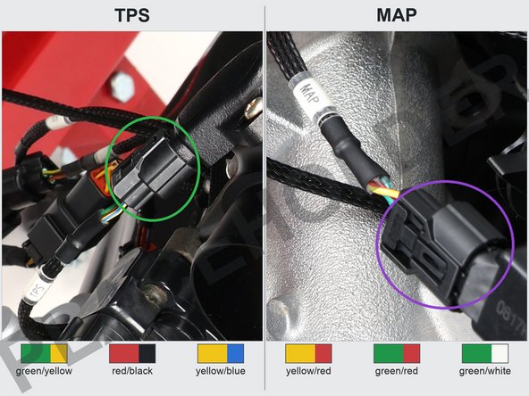
The TPS and MAP plugs look alike and sit close together. Verify by wire color. TPS: green/yellow, red/black, yellow/blue. MAP: yellow/red, green/red, green/white. A swapped MAP plug can be damaged at key-on with no warning light.
-
-
-
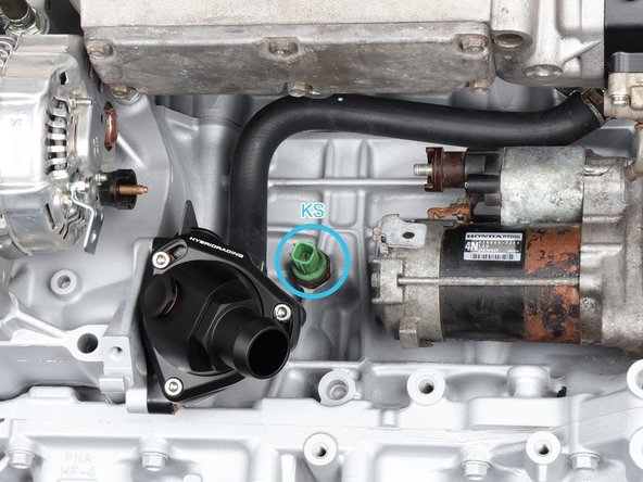
The harness ships with the green K20 knock plug prewired, the one that fits sensor 30530-PRB-A01 (K20A2). If that is the sensor on your engine, plug KS straight in under the intake manifold (KS ring).
-
If your engine has the black sensor, 30530-PPL-A01 (K20A3 or K24A), move the single KS terminal into the included replacement housing: pull its lock with a pick, slide the terminal out, seat it in the new housing until it clicks, tug to confirm, and push the lock back in.
-
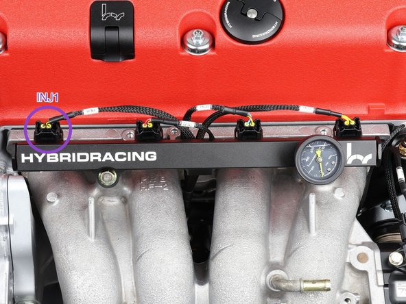
Drop the injector sub-harness down from the top and plug in INJ1 through INJ4, cylinder 1 at the chain side (labeled INJ1, violet ring).
-
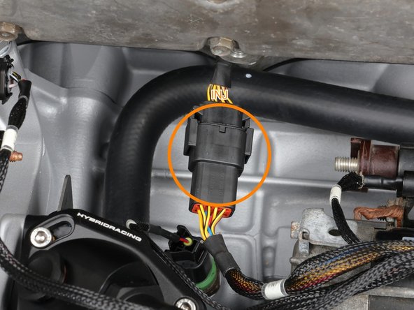
Run the injector sub-harness lead down between the manifold runners and plug it into the eight-wire quick disconnect under the manifold (labeled INJ, orange ring).
-
Later K24Z engines use a different injector connector style. We offer injector sub-harnesses that plug into the same quick disconnect, so swapping styles is one connector, no rewiring.
-
-
-
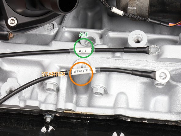
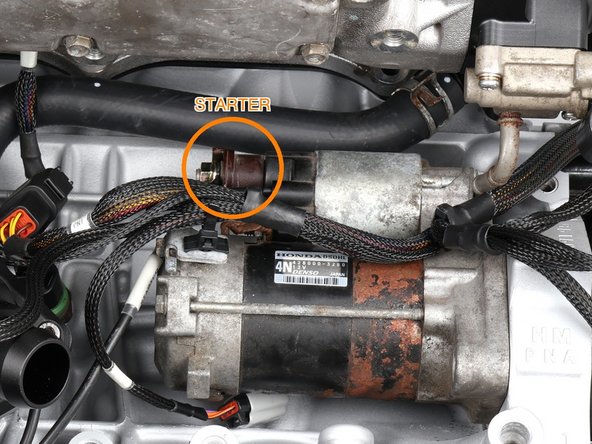
Land the heavy cable labeled STARTER, the starter battery feed, on the starter post with its M6 ring (the orange STARTER ring in the second photo marks the post). It is 8 AWG. Tighten the nut, then seat the boot back over the post.
-
Connect the small starter solenoid wire (labeled ST) at the starter solenoid. Its small boot sits beside the main post; go by the printed ST tag.
-
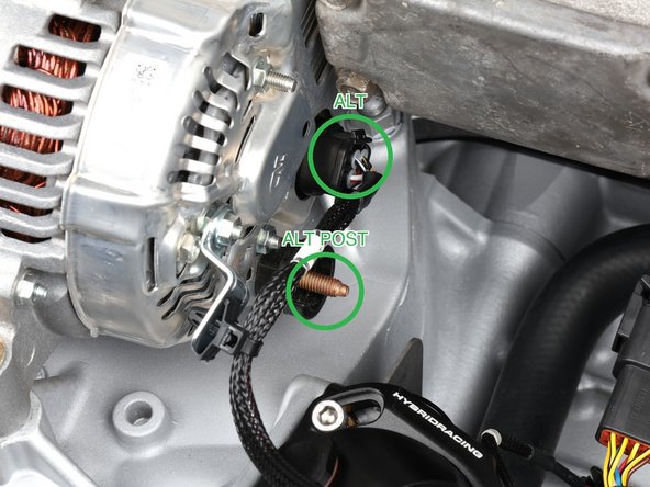
Plug the alternator connector (labeled ALT, green ring) into the back of the alternator.
-
Land the heavy cable labeled ALT, the alternator charge cable, on the alternator output post (the green ALT POST ring in the third photo marks the stud). The kit's rings fit common M6 and M8 studs. Tighten the nut, then seat the cover over the post.
-
Route both heavy power cables to a 12V source, away from the exhaust and pulleys, with a little slack at each end. On most Honda swap chassis that 12V source is the fuse box.
-
Fuse the alternator charge cable. The factory baseline is 100A; size to your alternator. An unfused 12V cable that shorts can start a fire.
-
-
-
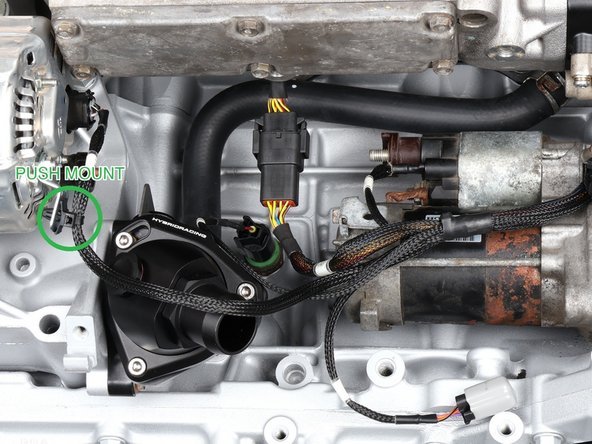
Zip tie the harness along the engine using the included push mounts in the OEM harness holes: two on the back side by the VTS and VTC solenoids, one by the starter, one at the alternator (green ring, marked PUSH MOUNT), extras where your build needs them. Leave the ties loose until the cabin section reaches the ECU in Step 11, then tighten.
-
Leave enough slack for the engine to rock on its mounts, never tight and never rubbing, and keep the harness off the exhaust and pulleys. Trim the tails after everything is tightened.
-
-
-
Route the cabin section through the firewall: an existing opening such as the heater core pass-through, the passenger side grommet where the fuse box wiring runs, or a hole you drill and grommet. Feed the small connectors through first and the big main connector (C101) last. Two people make this easy.
-
Whichever route you use, the harness passes through an intact grommet or edge protection, and gets tied on both sides so the weight of C101 never rests on sheet metal. If you drill, check both sides of the spot first, deburr the hole, and seat the grommet before you feed anything through.
-
At the ECU end the cabin section finishes in a small group of connectors. The plugs labeled A and B go to the ECU. Mate the rest to your conversion harness by printed label, then complete that harness's own power and ground instructions before the battery goes back on.
-
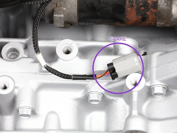
The three spare wires are built into the main harness and end in this small capped connector under the intake manifold (violet ring). At the other end they are already terminated in C101: purple at position 5, orange at 11, black/orange at 12. Leave them capped and tucked if you are not using them.
-
Close out what you left for later: plug in IAT once the intake is on, or tie that branch clear if the intake is still off; go back and tighten and trim every provisional zip tie; mount the ECU and support the harness at it so nothing hangs on the plugs.
-
Before the battery goes back on: every required connector latched, any moved terminals locked, main grounds installed, GND tight on bare metal, both heavy power cables landed and covered, firewall hole grommeted, unused connectors capped and tied. Then reconnect the battery.
-
Turn the key to ON before you crank. If you get a burning odor, smoke, heat, or a blown fuse, key off and disconnect the battery before touching anything. On K-Pro, confirm TPS, MAP, and ECT read sensibly in the software before the first start.
-
Do not start the engine until your tune or ECU setup is loaded. Expect a rough idle or relearn on first startup. If it cranks but will not start, check the CKP, CMPA, and CMPB plugs. If it idles rough or a reading looks wrong, check TPS and MAP.
-
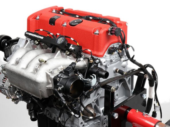
That is the full install. If the first start acts up, walk the printed labels one more time before you chase anything deeper. Admire a job well done.
That is the full install. If the first start acts up, walk the printed labels one more time before you chase anything deeper. Admire a job well done.
