Introduction
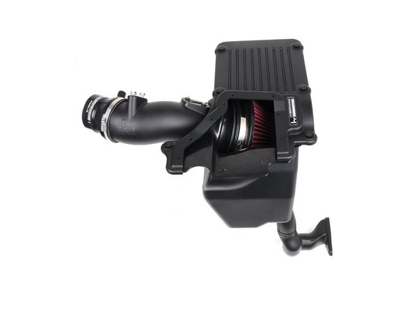
The Hybrid Racing Formula Cold Air Intake replaces the FK8's entire factory intake (airbox, air flow tube, and inlet duct) with a roto-molded airbox, a cone filter on a velocity stack, and a two-piece lower air inlet tube that feeds from the front of the car. You'll disconnect the battery, pull the stock intake out of the bay, then raise the front of the car and remove the driver-side front wheel and pull back the front inner fender to route the lower air inlet tube. Plan on 1.5 to 2 hours with common hand tools. Keep in mind that the two versions, Formula Street (76mm) and Formula Race (89mm), have different tuning requirements, so be sure to settle Step 1 before you start. Take the steps in order and it goes together cleanly.
-
-
This kit comes in two versions. Check the label on your box and know which one you have before you start:
-
Formula Street (76mm / 3"): HYB-CAI-01-25. The right choice for stock and lightly modified cars
-
Formula Race (89mm / 3.5"): HYB-CAI-01-26. Big-bore MAF housing and velocity stack, designed to support big power builds
-
The Formula Street (76mm) version runs on the stock ECU with no tune required, though Hybrid Racing recommends a FlashPro or similar tuning device to get the most out of it. The Formula Race (89mm) version changes what the MAF sensor reads and requires a matching calibration, so have your tune sorted before you drive the car.
-
This intake is not CARB approved. Check your state and local emissions regulations before installing.
-
Plan on 1.5 to 2 hours start to finish, including raising the front of the car and pulling the driver-side front wheel.
-
-
-
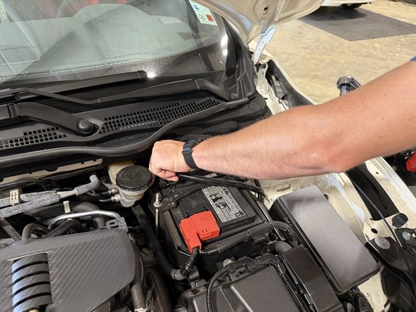
Set the parking brake and make sure the ignition is fully off.
-
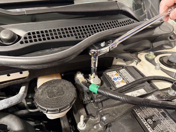
Disconnect the negative battery terminal and tuck the cable away from the post.
-
Always disconnect the negative terminal first. The negative cable has the battery sensor built in. Loosen the nut and lift by the terminal, not by the sensor or its connector.
-
Disconnecting the battery wipes radio presets and the clock, and some radios ask for an anti-theft code on reconnect. Have yours handy before you start.
-
-
-
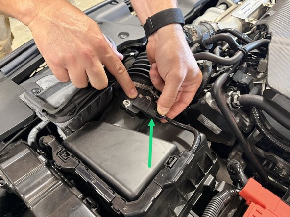
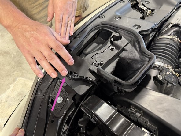
Unplug the MAF sensor connector at the air cleaner cover and lay the wiring over the front of the car, as shown in the third photo.
-
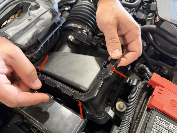
There are a few clips holding the wiring channel to the air cleaner cover. Pop them free with a flat head screwdriver. You come back to the wiring later. If you want to do the wiring now, jump down to the harness steps.
-
-
-
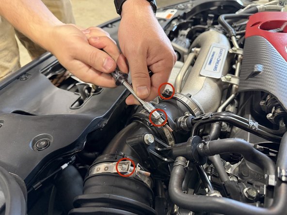
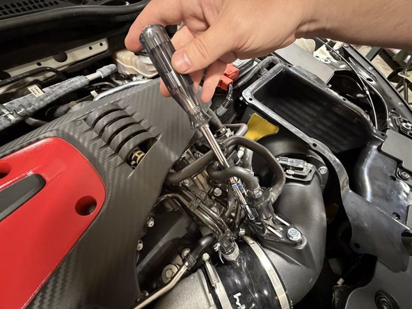
Loosen all of the hose clamps on the intake and inlet tubes. The stock clamps take a 5.5 mm socket or a flathead.
-
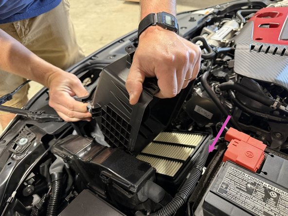
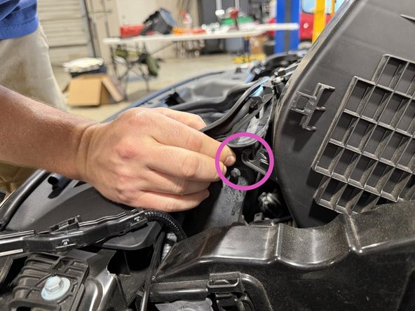
Release the clips and lift the air cleaner cover.
-
-
-
Remove the rubber inlet trim from the air cleaner cover. It stays in the car. You are just working it free to get the cover out, shown in the second photo.
-
Pull out the air cleaner cover.
-
Remove the air intake tube (the front duct) from the cover and pull it out of the car. It is held by soft tabs, so just pull and it comes out pretty easily. The third photo shows it fully removed.
-
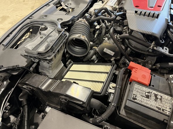
Lift the air cleaner element assembly (the panel filter) out of the lower housing.
-
The MAF sensor stays on the cover for now. You pull it later.
-
-
-
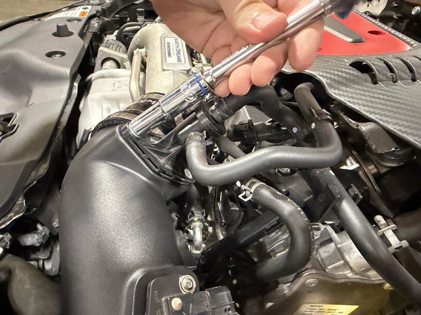
Loosen the two bolts and detach the air flow tube from the housing.
-
Disconnect the EVAP canister purge nozzle from the tube.
-
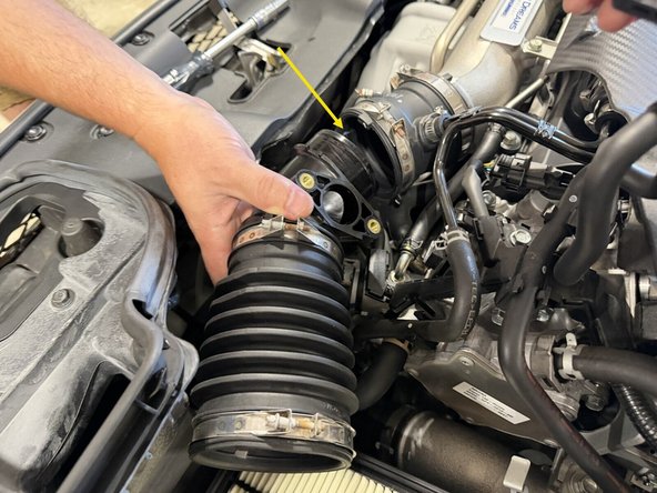
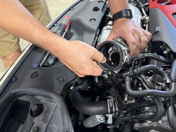
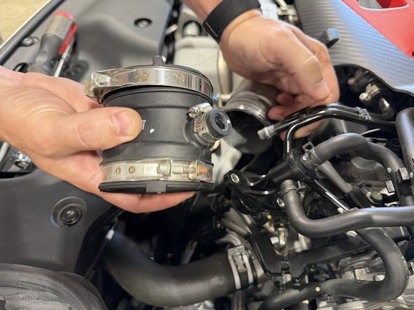
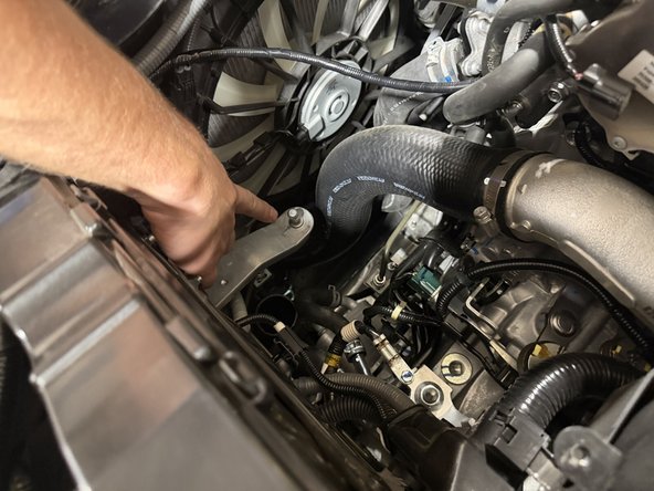
Loosen the clamps at the turbo inlet and work the tube free, then pull it out of the bay.
-
The factory band clamp is a one-time-use break-head clamp. If you ever return the car to stock, you need a new one.
-
-
-
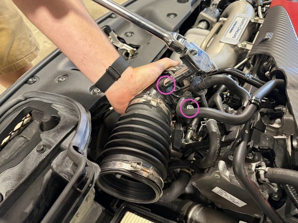
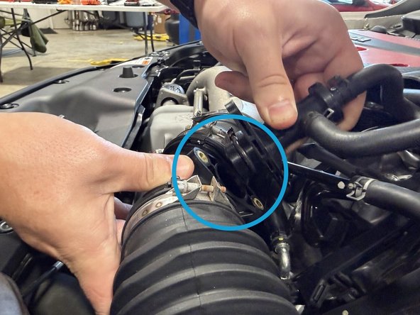
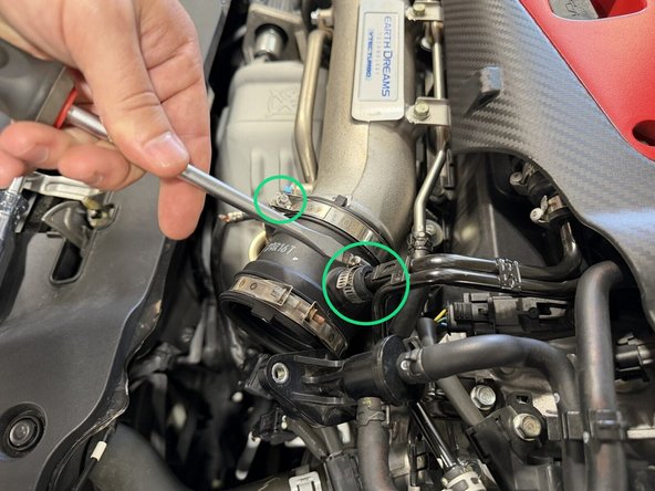
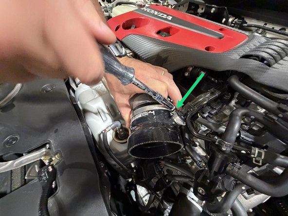
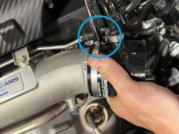
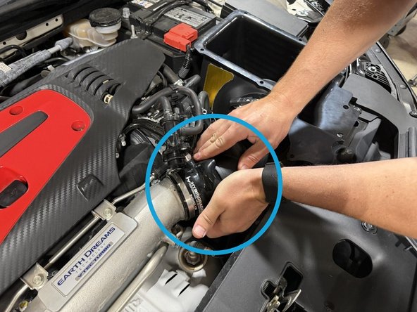
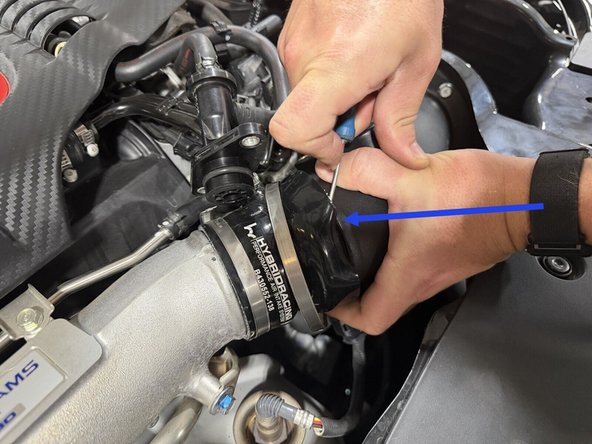
Loosen the coupler clamp at the turbo inlet, pull the coupler off, and remove the smaller hose clamp. Both are circled in the first image.
-
-
-
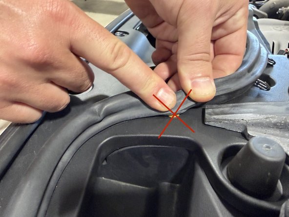
Be careful and go slow so you do not rip the seal or break the clips.
-
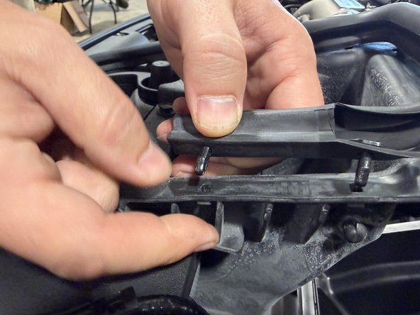
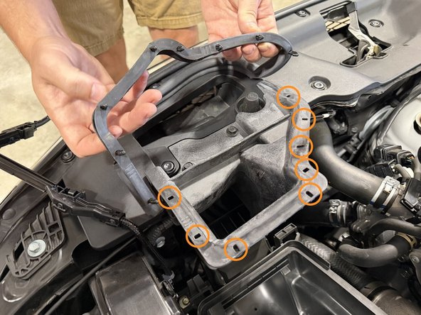
Unclip the rubber air intake seal from the air cleaner base rim. Only free as much as you need to remove the air intake tube.
-
You use this seal again later in the install, so set it aside where it stays clean.
-
OEM replacement if yours is torn: Honda air intake seal 17244-5BF-A01.
-
-
-
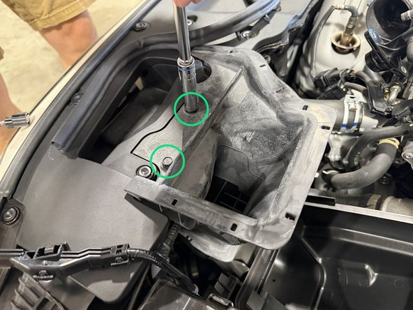
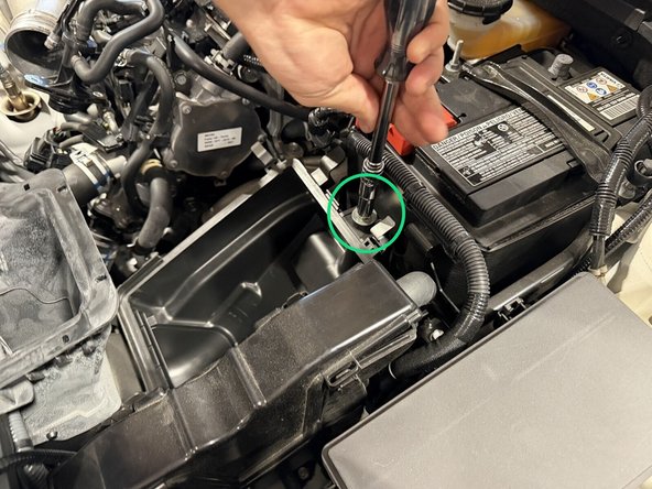
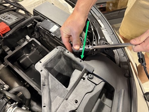
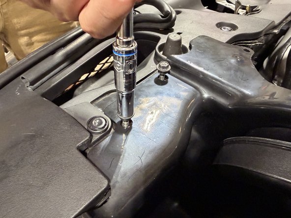
Unbolt the air cleaner case (4 bolts total).
-
Set the bolts in a safe place. You reuse them later.
-
-
-
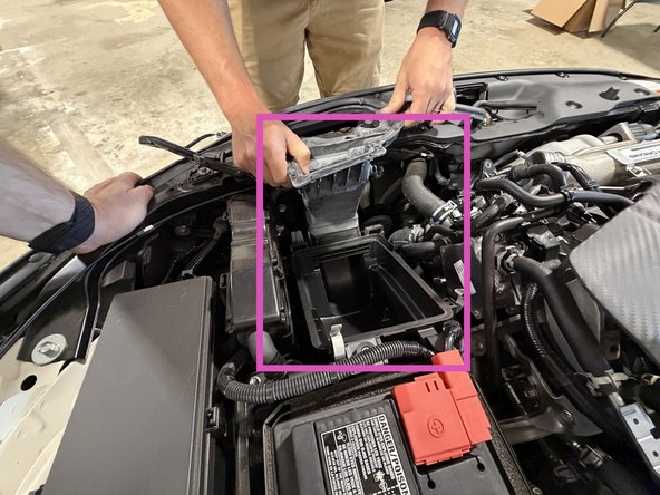
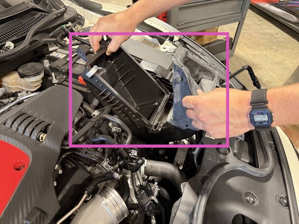
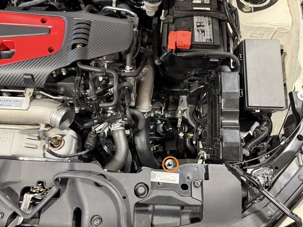
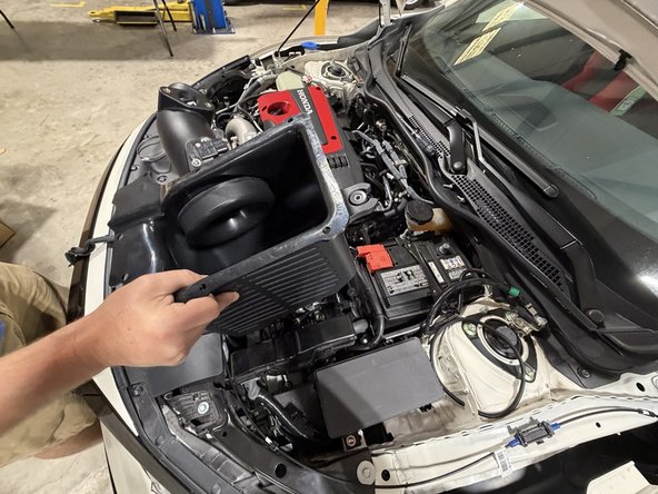
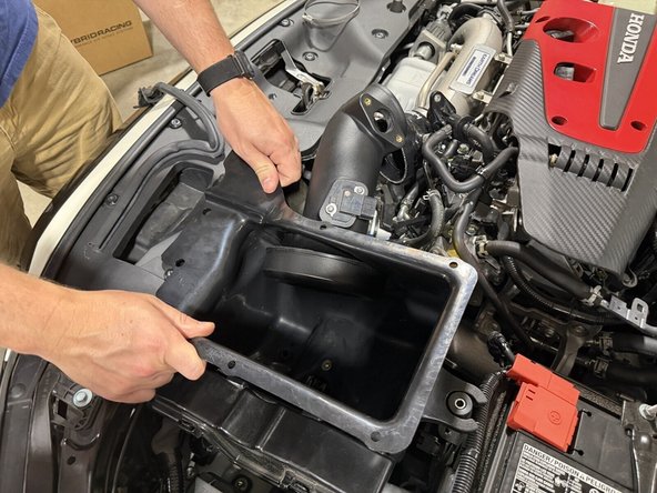
Lift out the inlet and filter housing. It rests on a small ball mount (circled in orange in the last photo), so give it a tug upward once all of the bolts are out.
-
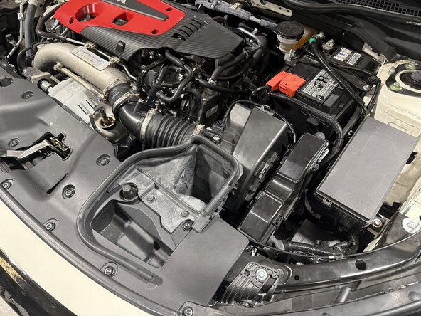
With everything out, the bay should look like the last photo.
-
-
-
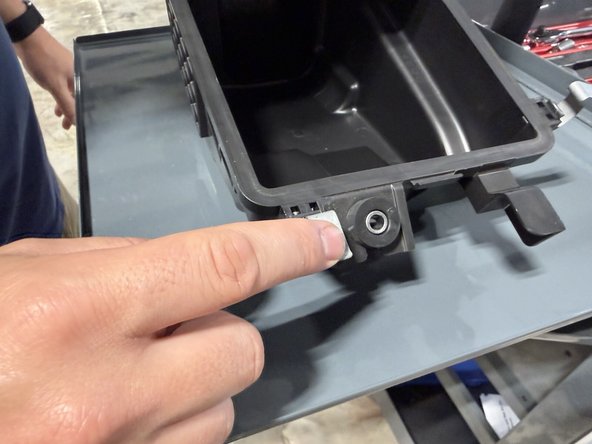
Remove the upper air cleaner mounting rubber and collar
-
Remove the lower rubber ball stud mount
-
Everything else stays with the stock air cleaner. Box it all up in case you ever return the car to stock.
-
OEM part numbers if you need: mounting rubbers 17212-P2J-J00 (x1) and 17212-P2J-000 (x1); mounting collars 17216-PN3-000 (x1).
-
-
-
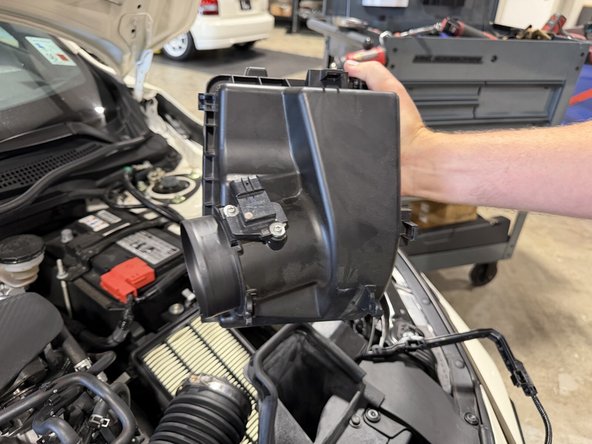
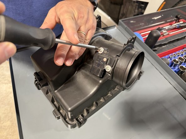
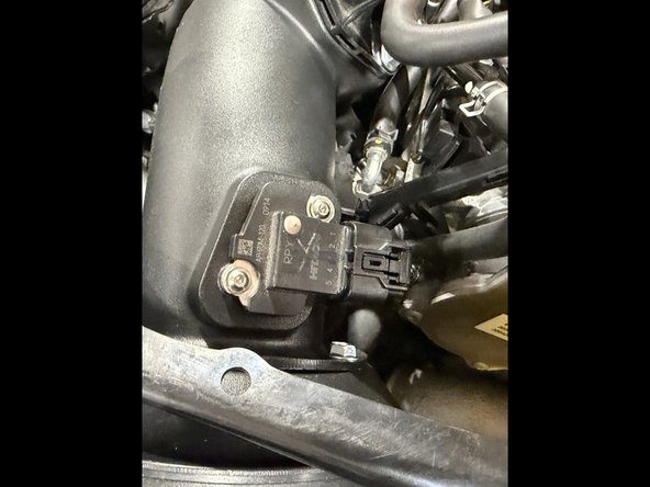
Remove the two screws and pull the MAF sensor off the stock cover. You reuse the MAF sensor and its gasket
-
Handle the MAF by its body only. Do not touch the sensor element, and set it somewhere clean.
-
OEM part numbers: air flow meter assembly 37980-RPY-G01, MAF gasket 37985-RAD-L11.
-
-
-
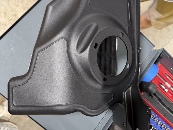
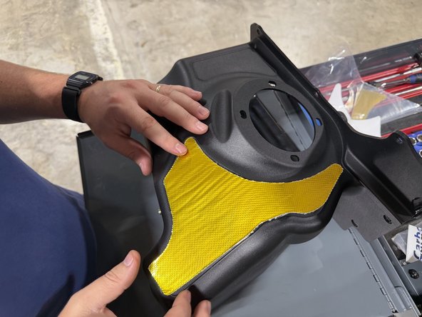
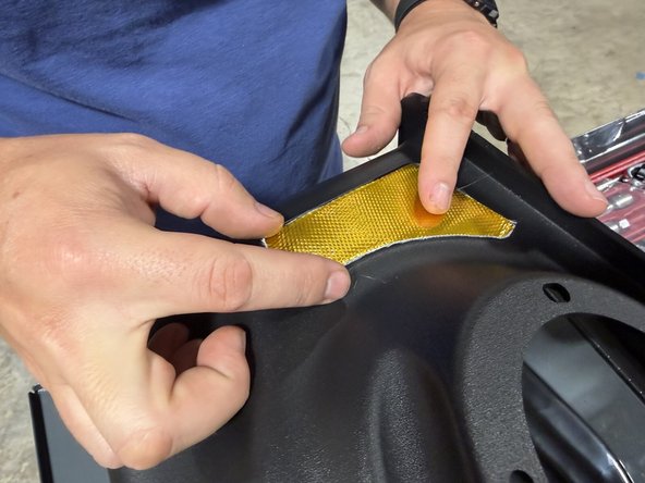
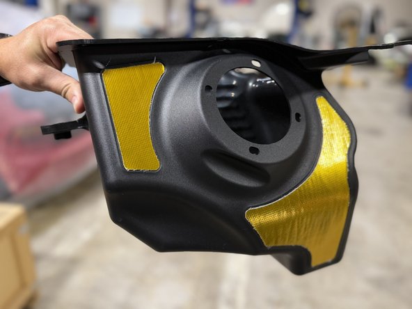
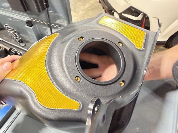
Grab your new intake box and the larger heat shield. Line the outside of the intake box with the pre-cut heat mat.
-
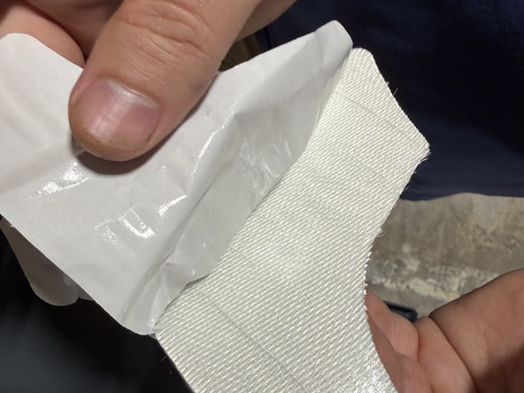
Peel the backing carefully and press it into the spot outlined on the intake box.
-
-
-
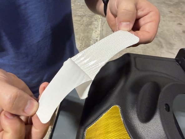
Grab the smaller heat strip, peel off the backing, and press it into its outlined shape on the intake box.
-
Smooth every piece down and check full coverage. No lifted edges or bubbles. You may have some stray fiberglass; if any strands are long, trim them a little, otherwise this step is done.
-
-
-
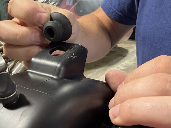
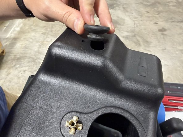
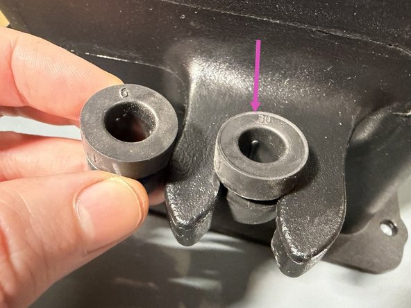
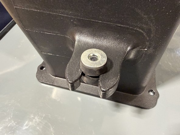
Insert the ball grommet into the bottom of the intake.
-
Install the rubber isolation grommet into the back of the intake. Make sure the ridge or lip on the grommet faces down, then insert the sleeve to hold it in place.
-
-
-
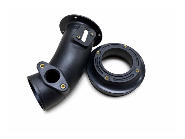
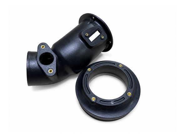
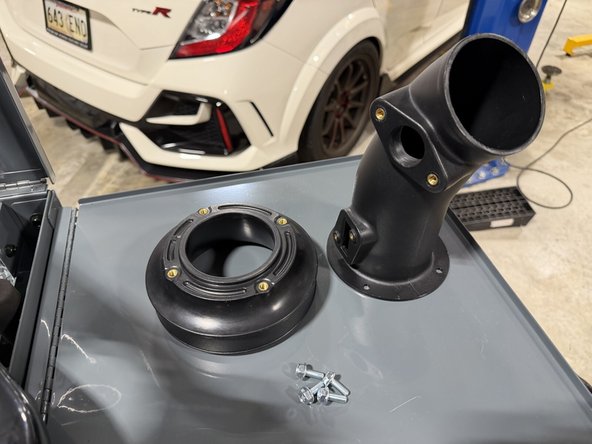
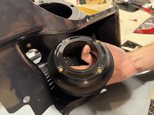
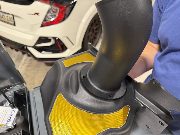
Locate your velocity stack and MAF housing inlet. Fit the velocity stack into the opening in the airbox from the inside.
-
The 76mm version has a raised lip that sits in the hole; the 89mm does not. Refer to the images in step 1 to confirm which one you have.
-
While holding the velocity stack as shown in the last image, seat it flush against the box from the outside, then move to the next step.
-
This step may require a second person to hold the inlet tube so you can get the first bolt started.
-
-
-
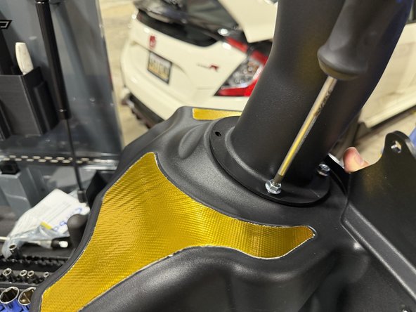
While holding the velocity stack, set the intake tube onto the airbox, lined up with the velocity stack bolt holes.
-
Fasten the tube to the box with the supplied screws. Get all the screws started loose before you snug any of them down. No thread locker needed.
-
-
-
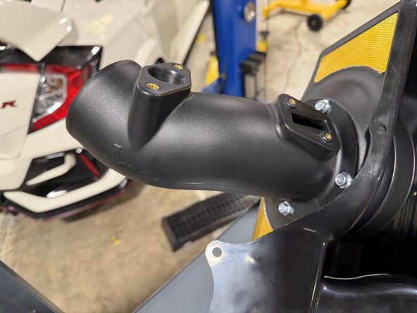
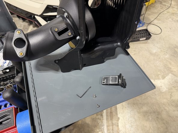
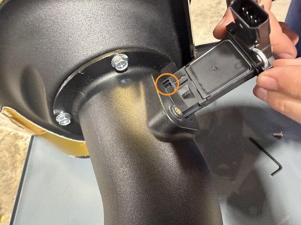
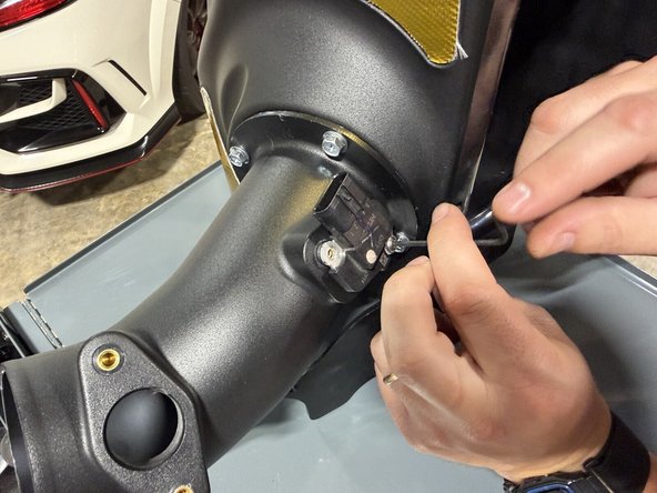
The kit includes new screws and an Allen key for the MAF sensor.
-
Insert the factory MAF sensor into the port on the Hybrid Racing intake tube, connector facing up like in the second image.
-
Secure it with the supplied hardware and Allen key.
-
The offset screw holes mean the sensor only fits one way. Seat it fully and square before tightening.
-
-
-
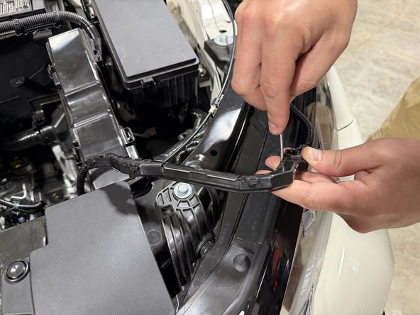
Unclip the wiring harness from its plastic guide along the front of the bay so it can be re-routed.
-
-
-
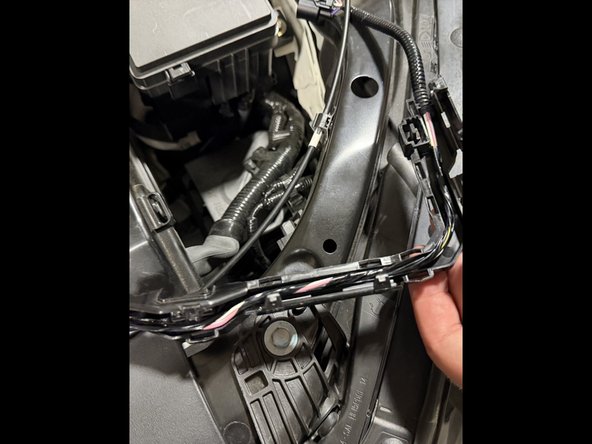
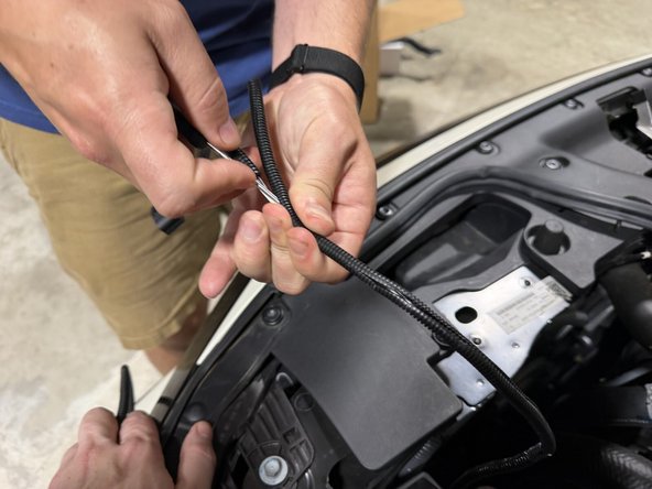
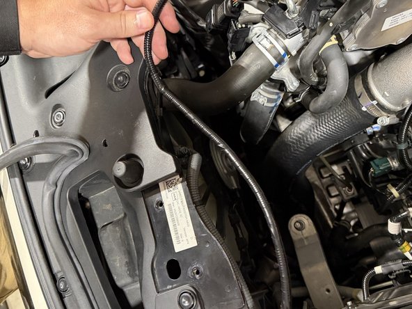
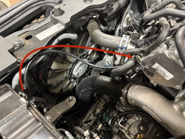
Slide the provided braided loom over the harness making sure to cover all of the wires. Use a little electrical tape to secure the loom and keep any wires from being damaged.
-
Route it along the front of the car and position it so the intake box can go in without snagging and the connector is easy to reach when you plug in the MAF sensor.
-
-
-
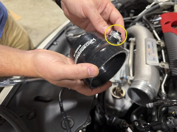
Fit the new coupler onto the turbo inlet and snug the clamp around its beaded edge.
-
Insert the tube into the inlet and snug the clamp.
-
-
-
Place the prepared Hybrid Racing intake into the car where the old one was. Pay close attention to the ball mount the box rests on.
-
Make sure the MAF sensor wiring clears the front of the intake box as you lower it down.
-
-
-
After lowering the airbox into the bay onto the factory mounting points, work the intake tube into the coupler.
-
You can use a small flathead to help pull the silicone over the inlet.
-
Snug is enough. There is no torque spec, and over-tightening a worm clamp on silicone will cut the coupler.
-
-
-
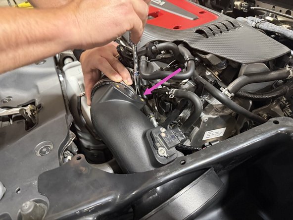
With everything aligned, position the breather hose tube into the inlet. Use the provided bolts to tighten the EVAP tube down.
-
Plug the MAF sensor in and make sure the wiring is properly routed so it will not contact anything.
-
-
-
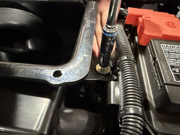
Bolt the airbox down at the factory mounting points. The factory spec for these bolts is 10 N-m (7 lb-ft).
-
If you want to install the lower air inlet tube, move on to step 26. If you would rather do it later, skip ahead to step 33.
-
-
-
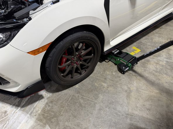
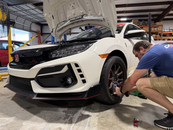
Raise the front of the car, support it properly, and remove the driver-side front wheel.
-
Never work under a car held only by a jack. Use jack stands or a lift.
-
This starts the lower air inlet tube install. The tube comes as two sections that snap together: the bumper section that mounts behind the front bumper, and the airbox section that feeds down through the airbox floor. The intake runs without it, but we recommend it. The second outside-air feed is part of how this intake makes its power.
-
-
-
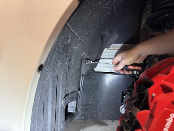
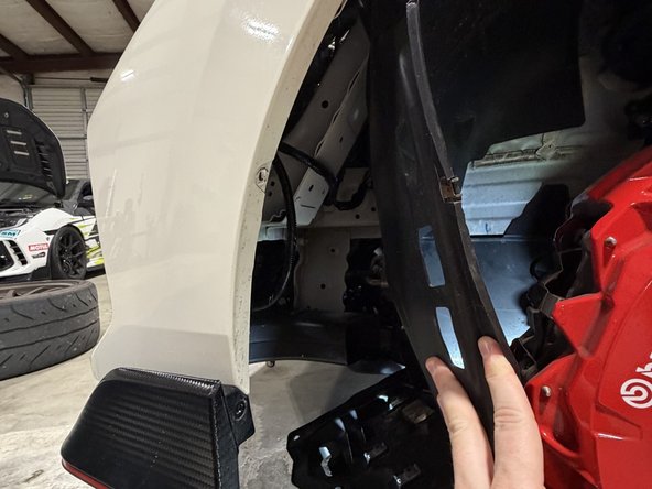
Remove these fasteners to pull the front half of the inner fender out of the wheel well.
-
-
-
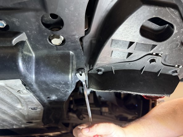
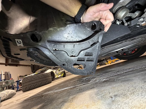
Remove the splash shield fasteners under the front of the car and drop the cover.
-
-
-
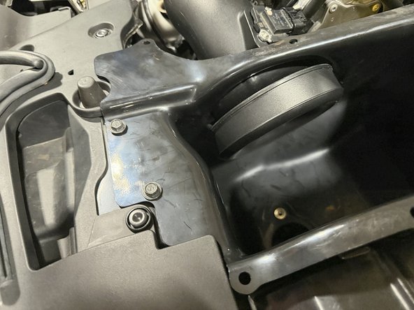
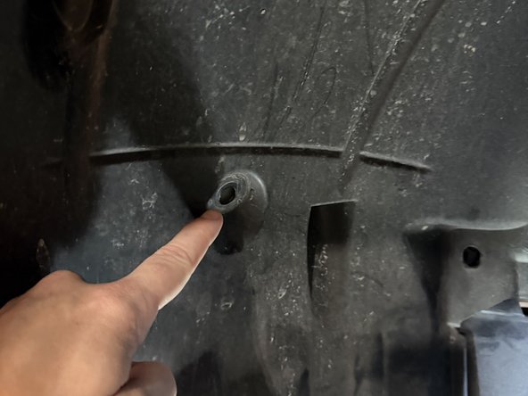
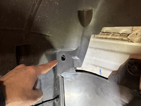
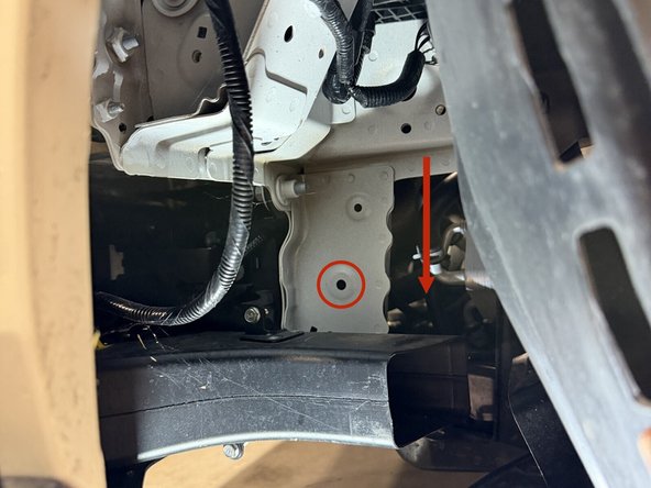
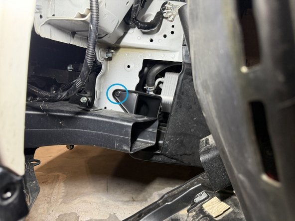
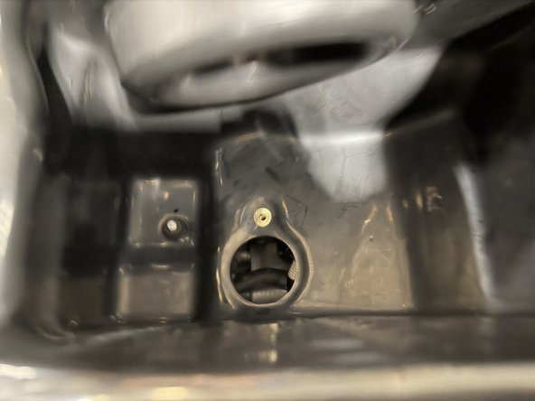
Pull back the inner fender and locate the position for the lower air inlet.
-
The lower air inlet mounts just above the factory brake duct.
-
This is the hole for the mounting of the lower air inlet.
-
-
-
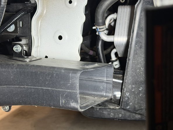
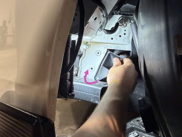
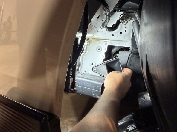
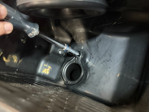
Install the lower section fully behind the bumper beam with the mounting hole pointing down. Once it's in, turn it clockwise until the hole lines up, and secure it. The push-in clip goes into the existing chassis hole.
-
-
-
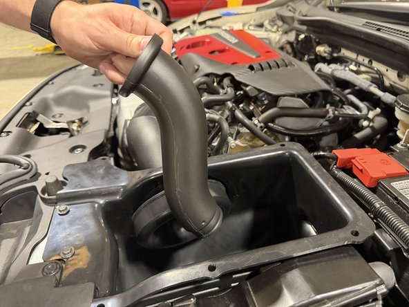
Feed the airbox section of the air inlet tube in through the opening in the airbox floor and snap it into the lower section below. This step is difficult and may take two people. Once the two sections are lined up, push up on the lower section and down on the airbox section until they snap together.
-
Install the supplied bolt to hold the airbox section to the box.
-
-
-
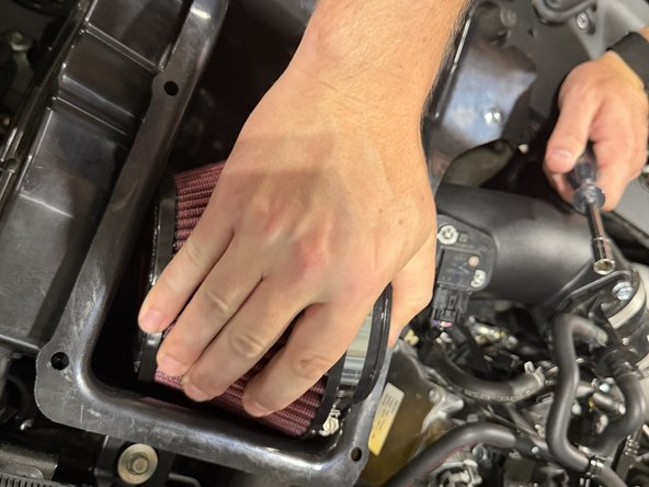
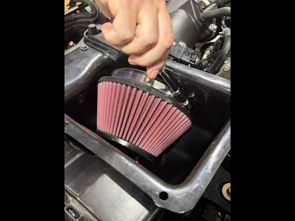
Slide the cone filter onto the velocity stack inside the airbox.
-
Tighten the filter clamp (8 mm).
-
Turn the filter so the clamp head faces the opening. Future filter service stays easy.
-
-
-
Press the rubber edge trim onto the top lip of the lid, working it around the full perimeter.
-
The trim seals the lid against the hood.
-
-
-
If you did the lower inlet: reinstall the engine undercover and front inner fender with their factory fasteners, then mount the front wheel, lower the car, and torque the lug nuts.
-
Clean the battery terminal contact faces and reconnect the negative terminal. Check that the clamp heads and breather hoses clear the hood liner before you close the hood.
-
Double-check every clamp, connector, and hose.
-
Running the Formula Race (89mm) housing? Upload your matching calibration BEFORE starting the car.
-
Take a gentle test drive. After the engine has fully heat-cycled, re-check both coupler clamps and every hose connection.
-
Admire a job well done.
-
After a battery disconnect the ECU relearns its idle. Let the car idle untouched until the radiator fan cycles before you drive. A slightly rough idle at first is normal, and the VSA, steering, TPMS, and collision-warning lights may be on. They clear on their own after a few seconds of driving straight above 9 mph.
-
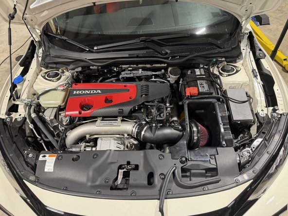
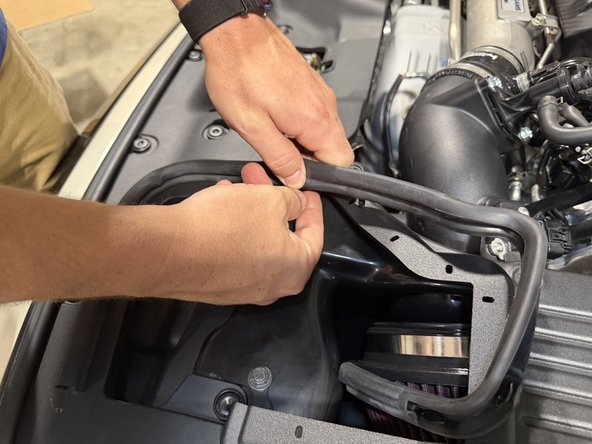
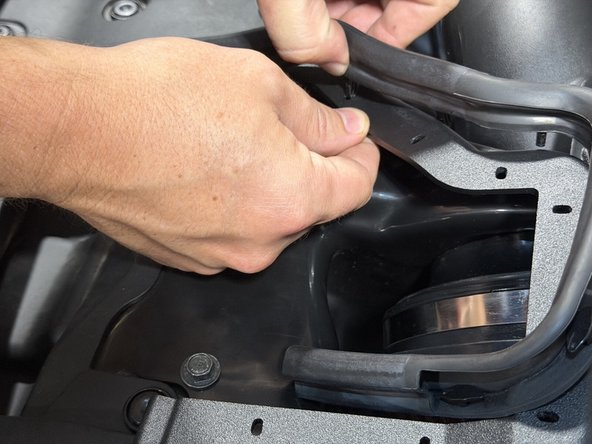
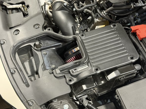
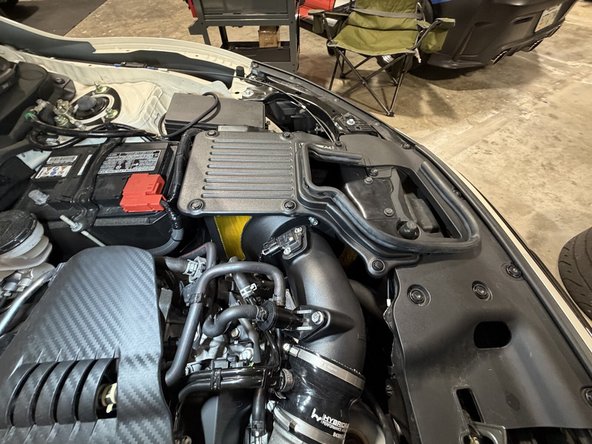
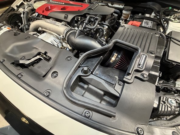
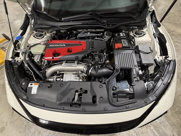
Re-check the clamps and mounting bolts after your first drive. Silicone couplers settle as they heat cycle. Admire a job well done.
Re-check the clamps and mounting bolts after your first drive. Silicone couplers settle as they heat cycle. Admire a job well done.
