Introduction
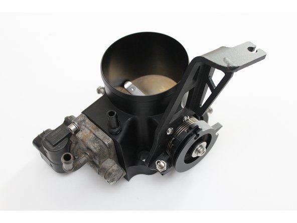
This install guide does not show all steps for installing this throttle body into a vehicle as it is compatible with many applications. However, this guide addresses many of the key features you should be familiar with when installing your new throttle body.
DO NOT REMOVE the graphite colored paint on the rim of the butterfly. This paint is used to seal the throttle body from a vacuum leak. If there is a small amount of flaking, still do not remove it. If it comes off and goes into the engine it will not hurt the engine since the paint is carbon based and will be consumed by the engine.
-
-
A big bore throttle body should not be used on a manifold that has not been bored to match or exceed the diameter of the throttle body (ie, a 70mm throttle body can be used on a manifold that’s bored to 74mm, but not on a manifold that’s bored to 65mm)
-
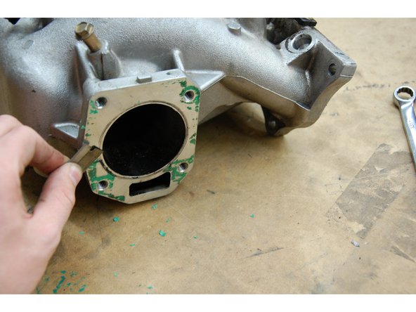
If you intend to bore the manifold yourself, use the supplied plastic gasket to trace out the bore before removing the studs.
-
Remove the gasket and check to see that the traced circle as shown in the figure.
-
-
-
The studs can be removed. The studs should be removed by threading two nuts onto the stud binding them together. Unscrew the inner nut to unthread the stud.
-
Note that a Honda M8 nut uses a 12mm wrench.
-
-
-
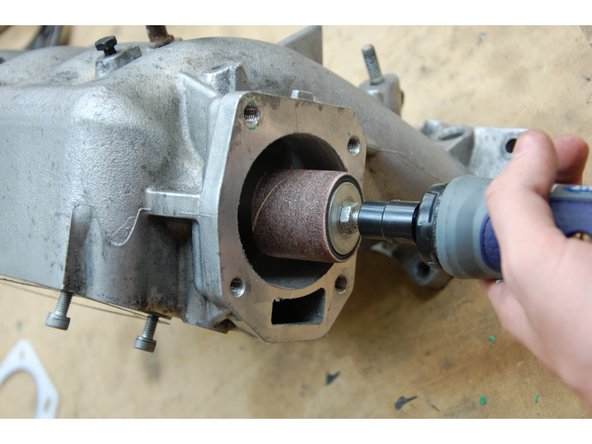
If you’re boring your own manifold, a die grinder or high-speed drill can be used with a grinding stone or sanding drum to bore the manifold from its 63mm stock size up to the outside edge of the circle you traced in step 1.
-
Be sure to remove any old gasket material from the mounting surface. If you are using a new intake manifold, disregard this step.
-
Remember that it’s better to open the hole up too big than too small. It’s very important to thoroughly clean your manifold after boring it as any aluminum dust left in the manifold could cause damage to your motor.
-
Blow out as much dust as possible with compressed air before cleaning.
-
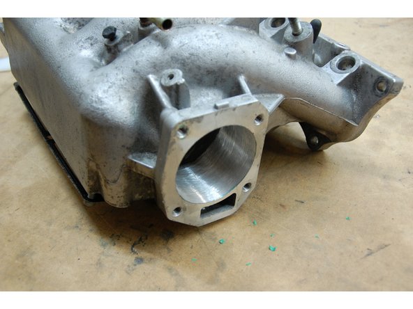
Next, flush out the remaining dust. Allowing water to flow through the manifold for a while will help to carry out debris that may not have been removed earlier. Make sure the manifold has thoroughly dried before installing it back on your motor.
-
The same steps should be followed for the PRB & RBC style intake manifolds. (PRB style shown)
-
-
-
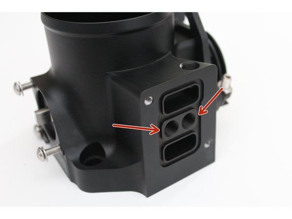
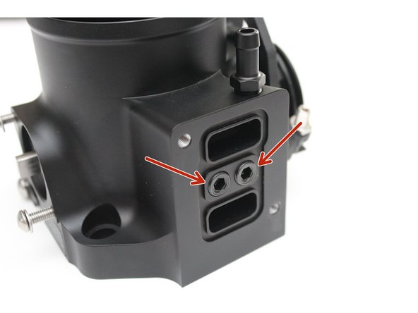
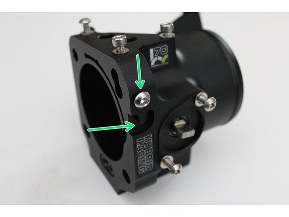
If you are not using the idle air control valve (IACV) you can use the supplied 1/8th NPT plugs to block off the essential air ports.
-
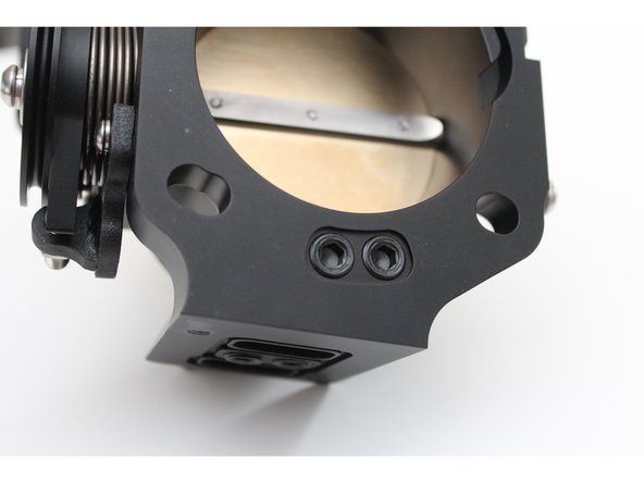
You must install and tighten the plugs in the lower IACV section, as well as the two on the mounting face of the throttle body.
-
Make sure the plugs are threaded ALL the way in on the mounting face BEFORE mounting the housing to an intake manifold. If the plugs are not all the way down it can prevent a seal causing a vacuum leak.
-
Be sure to use teflon tape or pipe thread sealant on the NPT fittings and let them cure BEFORE continuing.
-
If you are NOT using the IACV, it may be necessary for you to adjust the throttle stop screw. REFER TO STEP 10 for more information.
-
-
-
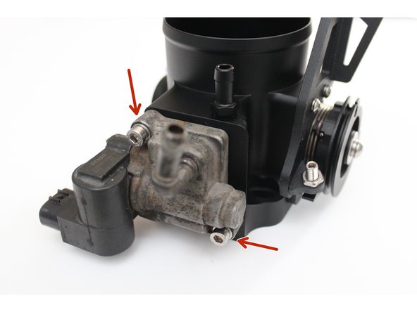
If you ARE using the idle air control valve (IACV) you will NOT be using the supplied 1/8th NPT plugs. If you have threaded them in, remove them otherwise the IACV will not function.
-
Place the OE IACV gasket into the machined groove on the bottom side of the throttle body. Next, place the IACV on the gasket aligning the two mounting holes.
-
Use the two supplied bolts and secure the IACV to the housing.
-
If you need to rotate the IACV so that the connector faces inward, do that now. (Factory configuration shown)
-
Do NOT connect the coolant line to the IACV if you have rotated it 180*.
-
-
-
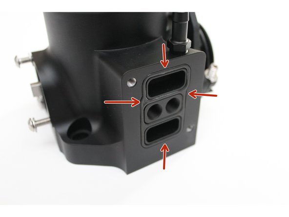
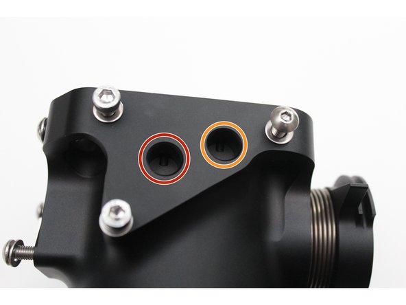
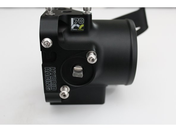
The port circled in RED is for the Purge Control Solenoid Valve. This is an emissions sensor used on the Acura RSX chassis. Insert a plug & retaining ring into this port if you are not using this sensor.
-
The port circled in ORANGE is for the MAP sensor. Install the MAP sensor into this port if you are using the PRB/PRC style intake manifold.
-
If you are using your HR throttle body on an intake manifold that has the MAP sensor located on the OE intake manifold (RRC/RBC) install the sensor in the factory location and install the supplied plug into the port circled in ORANGE.
-
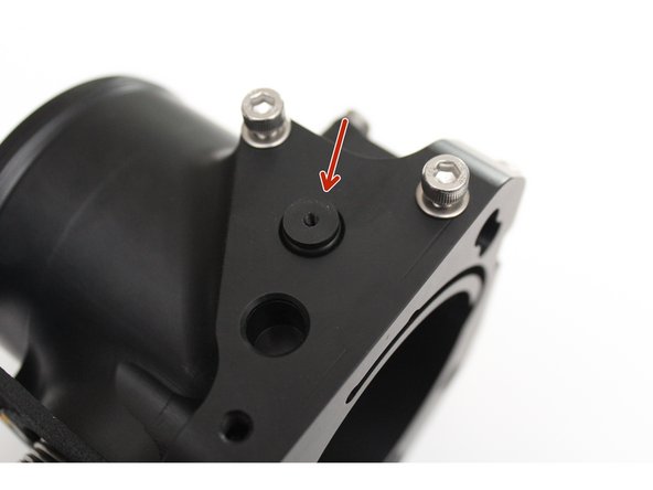
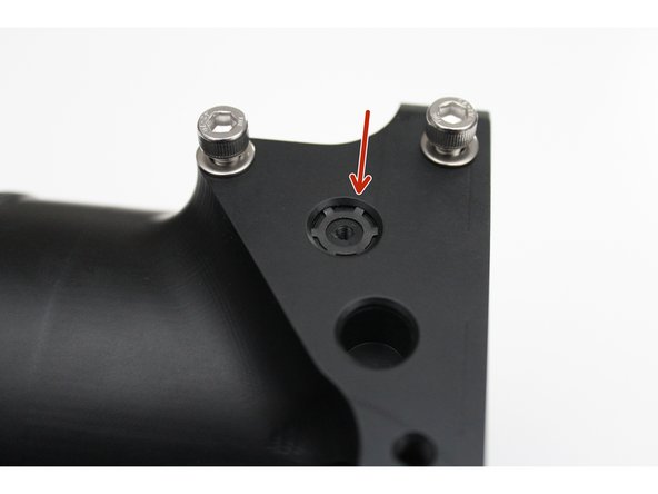
Insert the plug with the threaded hole facing up. If you do not, you will not be able to remove them without damaging the part.
-
Use the retaining rings to keep the plugs in place. Failure to do this can result in lost parts and vacuum leaks.
-
-
-
If you are installing your HR throttle body onto the Acura RSX, use the supplied bolt and groove (green arrow) to mount the OE throttle cable holder. (Optional)
-
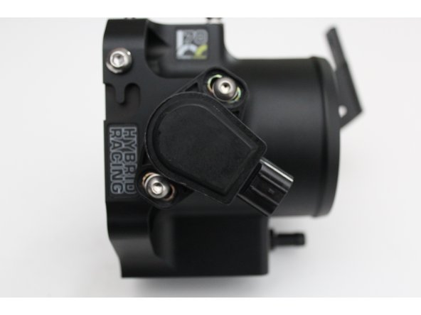
Remove your factory K-Series TP Sensor (K20A/A2/Z1) and use the supplied screws to bolt it in place.
-
Install the TP sensor and set it so that the mounting bolt is in the center of the TP sensor grooves. Snug them in place so you can calibrate the sensor when installation is complete.
-
If you do not have a TP sensor, contact Hybrid Racing for suggestions on which sensor to use.
-
-
-
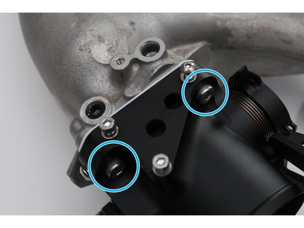
Using the supplied thermal gasket and stainless mounting hardware, attach your HR throttle body to your intake manifold of choice. (RBC shown)
-
There are two mounting bolts on the top and two on the bottom. (Bottom not shown)
-
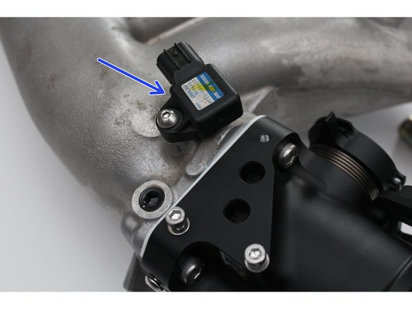
If you are using the RBC intake manifold, install the MAP sensor in the OE location. (Shown with arrow)
-
-
-
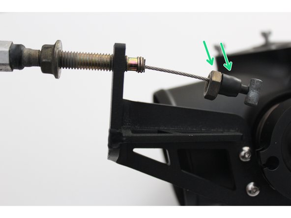
Begin by threading one of mounting nuts and rubber boot down towards the end of the cable. Insert the throttle cable through the bracket groove.
-
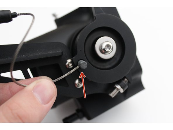
Insert the cable end into the throttle body rotor.
-
Insert the cable into the throttle body rotor groove so the cable is in line with the mounting bracket.
-
Disconnecting the throttle cable from the pedal assembly can aid in installation.
-
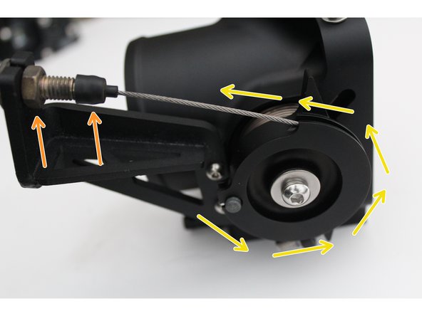
Thread the backing nut towards the bracket and adjust the cable placement so that the butterfly is fully open when the pedal is depressed to its maximum.
-
Tighten the throttle cable nuts together holding it to the throttle body bracket.
-
-
-
All Hybrid Racing throttle bodies are calibrated, sealed and locked before they are shipped to customers. Each unit is sealed and tested to ensure a leak-free butterfly. If you MUST adjust the idle set screw please understand this CAN affect how the car idles. If you are NOT using an IACV, this CAN result in idle surges.
-
Adjust the idle screw ONLY if you are NOT using an IACV.
-
If you ARE using the IACV and are experiencing idling issues, do NOT adjust this screw. Make sure your IACV is clean and spins freely when air is blown through it.
-
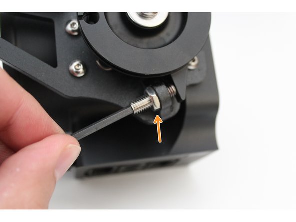
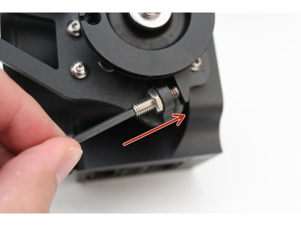
Loosen the locking nut on the throttle plate stop screw. These parts have thread lock on them.
-
Thread the throttle plate stop screw inward, to open the throttle plate. Once your desired idle has been achieved, apply thread lock and fully tighten the nut. Note that very SMALL adjustments can affect the idle in large ways.
-
-
-
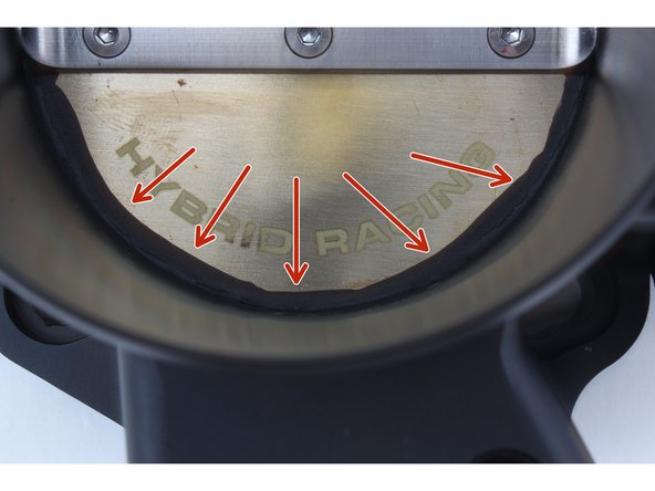
DO NOT REMOVE THE GRAPHITE COATING
-
The graphite coating is in place to prevent unwanted from air passing around the throttle plate. Removing this can cause idle issues.
-
Once the throttle body has been installed on the engine, calibrate the TPS and start the engine. Check for coolant or air leaks before driving.
-